Shop OBEX P1 Docs P2 Docs Learn Events
Help Understanding transistor output (TIP120/TIP31), why doesn’t it allow max V? — Parallax Forums

Help Understanding transistor output (TIP120/TIP31), why doesn’t it allow max V?

vanmunchvanmunch Posts: 568
edited 2014-02-01 00:42 in General Discussion
Hi everyone, I’ve been working on trying to figure out why I can’t control one of those tiny quadchopter motors as well as the quadchopter can. Most of this is new to me, so I’ve been learning a lot and making some progress, but I still can’t figure out why it’s only every partially on or partially closed.

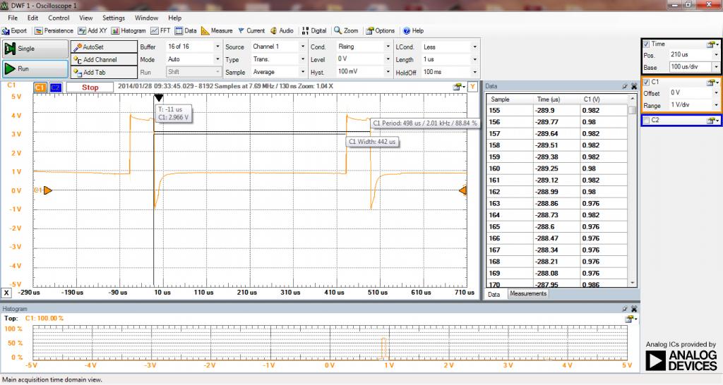
You can see in this picture the single that the quadchopter is receiving from the actual board.
QuadMotorWave.jpg

Note how the voltage doesn’t go below ~1V for the “off” position, but it does go fully open ~3.7V (single cell lipo battery) (Don't worry about the duty of the wave, I can control that.)


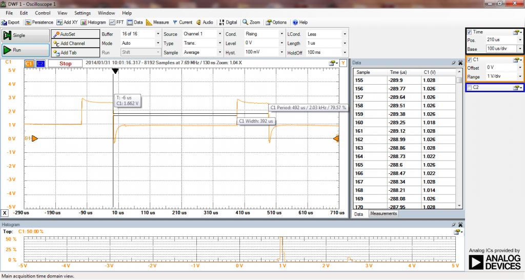
Now when I’m using a TIP120 it only goes to around 2.5V fully on. It should go to ~3.7V.
Tip120_20Duty.jpg


So I’m wondering:
1- Am I using the wrong transistor/MOSFET
2- Am I hooking it up wrong? (see below)
3- How do I create the same wave that the quadchopter’s board is natively doing?


My set-up following this layout (http://bildr.org/blog/wp-content/uploads/2011/03/tip120-solenoid.png):
MotorController.jpg
1024 x 546 - 98K
1024 x 546 - 98K
1024 x 576 - 80K

Comments

  • Peter JakackiPeter Jakacki Posts: 10,193
    edited 2014-01-31 08:05
    vanmunch wrote: »
    Hi everyone, I’ve been working on trying to figure out why I can’t control one of those tiny quadchopter motors as well as the quadchopter can. Most of this is new to me, so I’ve been learning a lot and making some progress, but I still can’t figure out why it’s only every partially on or partially closed.

    You can see in this picture the single that the quadchopter is receiving from the actual board.
    QuadMotorWave.jpg

    Note how the voltage doesn’t go below ~1V for the “off” position, but it does go fully open ~3.7V (single cell lipo battery) (Don't worry about the duty of the wave, I can control that.)


    Now when I’m using a TIP120 it only goes to around 2.5V fully on. It should go to ~3.7V.
    Tip120_20Duty.jpg


    So I’m wondering:
    1- Am I using the wrong transistor/MOSFET
    2- Am I hooking it up wrong? (see below)
    3- How do I create the same wave that the quadchopter’s board is natively doing?


    My set-up following this layout (http://bildr.org/blog/wp-content/uploads/2011/03/tip120-solenoid.png):
    MotorController.jpg
    TIP120 is a darlington and with a 1K base resistor you will only be driving it at I = V/R = 3.3V(Prop output) -1.2V(darlington Vbe) /1K = 2.1/1K = around 2ma. According to the datasheet the TIP120 will only have a Vce(sat) of 1.4V or so which means your 3.7 becomes 2.3V or so, just about right. Use a MOSFET, even a tiny SMD8 version or DPAK will work fine. That link doesn't work but I found another one and from what I read I can only confirm the old adage that a little knowledge is dangerous.
  • Duane C. JohnsonDuane C. Johnson Posts: 955
    edited 2014-01-31 09:42
    Hi vanmunch;
    I agree with verything Peter said about the crappy TIP-120.
    Just not suitable for these applications. The TIP120 has to much voltage drop.

    A much better part is the IRF3708 MOSFET.
    This can switch quite high currents without a heatsink. Easily 15A when driven with a Prop.
    Everyone should have the IRF3708 in their bag of tricks.

    Duane J
  • vanmunchvanmunch Posts: 568
    edited 2014-01-31 09:57
    TIP120 is a darlington and with a 1K base resistor you will only be driving it at I = V/R = 3.3V(Prop output) -1.2V(darlington Vbe) /1K = 2.1/1K = around 2ma. According to the datasheet the TIP120 will only have a Vce(sat) of 1.4V or so which means your 3.7 becomes 2.3V or so, just about right. Use a MOSFET, even a tiny SMD8 version or DPAK will work fine. That link doesn't work but I found another one and from what I read I can only confirm the old adage that a little knowledge is dangerous.

    Hi Peter, thanks for the info. So the Vce(sat) is the amount of voltage that's used to keep the gate "open"? I'm a little bit confused on how you got the 1.4V for the Vce(sat). I think the data sheet says that at 12ma at the base it's 2.0V.

    Anyhow, I tried a ZVN2110A MOSFET that I had in a kit, but the results were worst than before.
    WIth_ZVN2110A.jpg

    I thought that the max voltage was 60V, but it appears to be only 2.4V?

    Do you know of an example MOSFET that would work for driving ~2A at 3.7V so that I know what I'm looking for?

    I was also wondering what you meant about the little bit of knowledge, did you mean that the example they gave was incorrect? That you shouldn't use a TIP120 for driving a motor? I know that I'm dangerous with what I know right now, but I hope not to be. :)

    Thanks for your help! :)
    1024 x 546 - 98K
  • vanmunchvanmunch Posts: 568
    edited 2014-01-31 10:00
    Hi vanmunch;
    I agree with verything Peter said about the crappy TIP-120.
    Just not suitable for these applications. The TIP120 has to much voltage drop.

    A much better part is the IRF3708 MOSFET.
    This can switch quite high currents without a heatsink. Easily 15A when driven with a Prop.
    Everyone should have the IRF3708 in their bag of tricks.

    Duane J

    Thanks Duane, I was writting Peter back and didn't see this before I made my post. I'll take a look at the IRF3708. :)

    Got it TIP-120 == crappy :)
  • LoopyBytelooseLoopyByteloose Posts: 12,537
    edited 2014-01-31 10:03
    Yep, the TIP120, TIP125, and TIP130 darlington pairs all seem to have a 2 volt drop at saturation. In a PNP/NPN H-bridge, that becomes a dreadful 4 volt drop.

    Either use MOSfets, or provide a higher voltage power source.

    Arduino loves to give examples using the TIP120 to the uninformed <sigh>.
  • vanmunchvanmunch Posts: 568
    edited 2014-01-31 10:32
    Ok, thank you all. I think I'm getting someplace. I saw so many examples using a TIP120 that I thought I was messing up the wiring, because why would anyone use something that caused you to loose so much voltage?

    Using the IRF3708 as a starting point I found the FDU3N40TU that I think will work for me. If I'm reading the data sheet correctly, it will do 2A continuously. The rds on is 3.4 ohms compared to 12m ohms that the 3708. I don't know how much that matters. Any advice?
    http://www.mouser.com/ProductDetail/Fairchild-Semiconductor/FDU3N40TU/?qs=sGAEpiMZZMshyDBzk1%2fWiw3ktwnhg7wCL%2fcMbgLH3Qo%3d
  • davejamesdavejames Posts: 4,047
    edited 2014-01-31 12:02
    vanmunch wrote: »
    Got it TIP-120 == crappy :)

    As with any device, it's only crappy when used in an incompatable application. Otherwise, the TIP-120 is a typical darlington that's had a long and useful life.
  • vanmunchvanmunch Posts: 568
    edited 2014-01-31 12:14
    davejames wrote: »
    As with any device, it's only crappy when used in an incompatable application. Otherwise, the TIP-120 is a typical darlington that's had a long and useful life.

    Hey Dave, thanks. I should have specified as being a poor choice for a motor controller. :) What would it be a good application for a TIP-120?

    Dave
  • Duane C. JohnsonDuane C. Johnson Posts: 955
    edited 2014-01-31 12:28
    Hi vanmunch;
    vanmunch wrote: »
    OUsing the IRF3708 as a starting point I found the FDU3N40TU that I think will work for me. If I'm reading the data sheet correctly, it will do 2A continuously. The rds on is 3.4 ohms compared to 12m ohms that the 3708. I don't know how much that matters. Any advice?
    http://www.mouser.com/ProductDetail/Fairchild-Semiconductor/FDU3N40TU/?qs=sGAEpiMZZMshyDBzk1%2fWiw3ktwnhg7wCL%2fcMbgLH3Qo%3d
    no No NO NO!!!
    The RDS(on) is the important specification. Then the required gate voltage and other things.
    Yes the IRF3708 has a 62A current rating but we don't really care about that.
    The IRF3708 has an RDS(on) of about 15mΩ.
    This is important because if you want to switch 2A of current:
    ID * RDS(on) = VDS(on)
    2A * .015Ω = 0.03V
    ID2 * RDS(on) = PD Power Dissipation
    2A2 * .015Ω = 0.06W Really low so it won't get hot.
    Clearly no heat sink would be required.
    However with the ZVN2110A which has an RDS(on) of 4Ω:
    ID * RDS(on) = VDS(on)
    2A * 4Ω = 8V
    ID2 * RDS(on) = PD Power Dissipation
    2A2 * 4Ω = 16W This will get HOT.
    Even a heat sink would not help this.
    The FDU3N40TU is only slightly better with an RDS(on) of 3.2Ω:
    ID * RDS(on) = VDS(on)
    2A * 3.2Ω = 6.4V
    ID2 * RDS(on) = PD Power Dissipation
    2A2 * 3.2Ω = 12.8W Not quite as HOT but still will kill it even at 2A.

    Take a look at the lists of parts on my web page.
    Many of the parts people have used on this forum are listed there.
    Click the part# on the left for the spec sheet.
    These have generally been sorted by VG.
    On the right are graphs I have personally measured.

    Anyway:
    First look at the RDS(on) to calculate the VDS(on) voltage drop and PD power dissipation.
    If either is to high, choose a part with lower RDS(on).
    Then go on to VDSS and VGS suitable for your application.

    BTW, why do they make all those weak parts. Because there are many applications where high currents are not needed.
    Even the high current parts will need a heatsink when switching very high currents.

    And there are lots of other parameters to consider, but for now stick with RDS(on).

    Duane J
  • vanmunchvanmunch Posts: 568
    edited 2014-01-31 13:29
    Hi vanmunch;
    no No NO NO!!!
    The RDS(on) is the important specification. Then the required gate voltage and other things.
    Yes the IRF3708 has a 62A current rating but we don't really care about that.
    The IRF3708 has an RDS(on) of about 15mΩ.
    This is important because if you want to switch 2A of current:
    ID * RDS(on) = VDS(on)
    2A * .015Ω = 0.03V
    ID2 * RDS(on) = PD Power Dissipation
    2A2 * .015Ω = 0.06W Really low so it won't get hot.
    Clearly no heat sink would be required.
    However with the ZVN2110A which has an RDS(on) of 4Ω:
    ID * RDS(on) = VDS(on)
    2A * 4Ω = 8V
    ID2 * RDS(on) = PD Power Dissipation
    2A2 * 4Ω = 16W This will get HOT.
    Even a heat sink would not help this.
    The FDU3N40TU is only slightly better with an RDS(on) of 3.2Ω:
    ID * RDS(on) = VDS(on)
    2A * 3.2Ω = 6.4V
    ID2 * RDS(on) = PD Power Dissipation
    2A2 * 3.2Ω = 12.8W Not quite as HOT but still will kill it even at 2A.

    Take a look at the lists of parts on my web page.
    Many of the parts people have used on this forum are listed there.
    Click the part# on the left for the spec sheet.
    These have generally been sorted by VG.
    On the right are graphs I have personally measured.

    Anyway:
    First look at the RDS(on) to calculate the VDS(on) voltage drop and PD power dissipation.
    If either is to high, choose a part with lower RDS(on).
    Then go on to VDSS and VGS suitable for your application.

    BTW, why do they make all those weak parts. Because there are many applications where high currents are not needed.
    Even the high current parts will need a heatsink when switching very high currents.

    And there are lots of other parameters to consider, but for now stick with RDS(on).

    Duane J

    This is great! and your website is such a great resource! :) Thank you for laying out the math, I understand now how important Rds is and why.

    So, to continue, the voltage threshold (Vth) is the amount of voltage that needs to be exceeded by the gate voltage (Vgs) in order for current to flow through the MOSFET. In the case of the IRF3708, the MOSFET allows current to flow once the Vth of 2.0V is applied to the gate. Applying more voltage to the gate continues to decreases the resistance of the gate.

    So, if I have a NTE2395 with a Vgs min of 2.0 and a max of 4.0, I would need to apply between 2 to 4v for it allow current to flow through?
    http://www.nteinc.com/specs/2300to2399/pdf/nte2395.pdf

    Am I following this correctly? Thank you very much for your help.
    Dave
  • Peter JakackiPeter Jakacki Posts: 10,193
    edited 2014-01-31 14:20
    vanmunch wrote: »
    This is great! and your website is such a great resource! :) Thank you for laying out the math, I understand now how important Rds is and why.

    So, to continue, the voltage threshold (Vth) is the amount of voltage that needs to be exceeded by the gate voltage (Vgs) in order for current to flow through the MOSFET. In the case of the IRF3708, the MOSFET allows current to flow once the Vth of 2.0V is applied to the gate. Applying more voltage to the gate continues to decreases the resistance of the gate.

    So, if I have a NTE2395 with a Vgs min of 2.0 and a max of 4.0, I would need to apply between 2 to 4v for it allow current to flow through?
    http://www.nteinc.com/specs/2300to2399/pdf/nte2395.pdf

    Am I following this correctly? Thank you very much for your help.
    Dave

    Vth is a guide as to when it just starts to conduct, but it's a useless figure IMO, check the Rds(on) as Duane mentioned and in fact just consider the device list he referred to rather than trying to work this out yourself at present.
  • Beau SchwabeBeau Schwabe Posts: 6,566
    edited 2014-01-31 15:15
    Vth might be applicable in a re-generative application where the goal is to keep it just inside or at the edge of conduction (linear mode) where the transistor is most sensitive to small changes on the input (gate)
  • Duane C. JohnsonDuane C. Johnson Posts: 955
    edited 2014-01-31 15:41
    Hi vanmunch;
    vanmunch wrote: »
    So, to continue, the voltage threshold (Vth) is the amount of voltage that needs to be exceeded by the gate voltage (Vgs) in order for current to flow through the MOSFET.
    Pretty much. Note that the spec specifies what small current will flow, in the NTE2395 this is 250µA. (There is a typo in that spec, it says 250?A, I can't display the special character. but it should be 250µA). Some parts are specified at 1mA.
    In the case of the IRF3708, the MOSFET allows current to flow once the Vth of 2.0V is applied to the gate. Applying more voltage to the gate continues to decreases the resistance of the gate.
    Yes, in this case 250µA will flow with VGS somewhere between 0.6V and 2V. Prudent designers would design to the maximum value of 2V. The Prop then has, usually. another 1.3V, (3.3V - 2V), to cause good conduction. Not the best conduction but quite acceptable.
    So, if I have a NTE2395 with a Vgs min of 2.0 and a max of 4.0, I would need to apply between 2 to 4v for it allow current to flow through?
    Yes, just barely to flow, according to the spec. If you are using a Propeller, which nominally outputs a Vpin(HI) of 3.3V the NTE2395 may not turn on at all. The NTE2395 is what we call a "Standard Level" VGS MOSFET. These are usually driven with a 10V gate drive. There is no RDS(on) specified for anything less than 10V. Unsuitable for use with a Prop or Stamp.

    The Stamp, 5V, is able to effectively drive what are called "Logic Level" MOSFETs. There will clearly be an RDS(on) specified, usually; for 4.5V or so.

    The Prop, 3.3V, is able to effectively drive what are called "Sub Logic Level" MOSFETs. There will clearly be an RDS(on) specified, usually; for 2.7V or so. In this case 2.8V for the IRF3708. Often the RDS(on) will be lower if the gate voltage is higher.

    BTW, there are specialized MOSFETs that can operate on even lower gate voltages. They just keep getting better. Yea!
    Am I following this correctly? Thank you very much for your help.
    Dave

    I think so.

    But seriously, Bite The Bullet. Order say 10 or so of the IRF3708 from DigiKey or Mouser, about $14. These, at a minimum, are a "Required" component in the parts stash.

    There are a few others I like with a smaller TO-251 or IPAK package:
    RFD14N05L Not as high a current but a much smaller package. (Ok, there is no RDS(on) @ 2.7V entry in the spec but I know it works well on the Prop as I measured them, (can't use it in a commercial application running on 3.3V). Pretty cheap at $16 for 25 of them.

    Duane J
  • Mark_TMark_T Posts: 1,981
    edited 2014-01-31 17:29
    Vth is the voltage at which the device turns fully _OFF_. That is to guarantee a device is off you have to drive
    it below the minimum Vth. Its absolutely irrelevant to the device being ON. Crudely speaking a device is on when
    the gate is above the plateau voltage (seen the graphs in datasheets of Vgs against gate charge). However
    most graphs in datasheets are "typical values" so you cannot rely on them except to get a feel for the parameters,
    you always go back to the Rds(on) spec to see what Vgs is needed to guarantee behaviour.
  • vanmunchvanmunch Posts: 568
    edited 2014-01-31 17:35
    Everyone, thank you for the help. I'm going to place an order for those two tomorrow, any others that might be good to have at hand for use with the propeller? Is their a special flywheel diode that I should buy to use with it while running a motor?

    Duane, thank you especially for laying everything out so clearly.

    Dave
  • Peter JakackiPeter Jakacki Posts: 10,193
    edited 2014-01-31 19:09
    Vth might be applicable in a re-generative application where the goal is to keep it just inside or at the edge of conduction (linear mode) where the transistor is most sensitive to small changes on the input (gate)

    I guess what I'm saying is that in the context of this forum we are normally discussing switching apps and everyone seems to see and quote the Vth figure and expect to switch many amps at that voltage, so it's a very misleading figure for switching. Now Rds(on) is much better but also like buying a house you can't just look at the beuatiful gate or the well equipped kitchen, you have to see it as a whole (or you might end up with a hole).
  • Duane C. JohnsonDuane C. Johnson Posts: 955
    edited 2014-01-31 20:20
    Hi vanmunch;
    vanmunch wrote: »
    Everyone, thank you for the help. I'm going to place an order for those two tomorrow, any others that might be good to have at hand for use with the propeller? Is their a special flywheel diode that I should buy to use with it while running a motor?
    I have 3 other MOSFETs that have been very usefull to have in the parts stash in this order:
    1. BS108 with guaranteed RDS(ON) of VGS at 2.8V & 2.0V.
    2. ZVNL120A with guaranteed RDS(ON) of VGS at 3.0V.
    3. And of course the venerable 2N7000. Works well with the Prop although the spec doesn't guarantee it but I have measured them.

    And many others for one reason or another.

    I don't invest in gold, I invest in silicon.

    In general, the snubber diode is fairly uncritical. Just use a silicon rectifier diode with a peak current rating equal to the maximum current flowing through the coils of the relay or small motor if you don't switch to rapidly. Any of the standard 1A 1N400x series usually work nicely, they have a pretty high peak current rating.
    (If fast switching is needed get back to us.)
    Oh, and you don't want to use a Schottky diode.
    Duane, thank you especially for laying everything out so clearly.
    Dave

    Thanks, just trying to help!

    Duane J
  • LoopyBytelooseLoopyByteloose Posts: 12,537
    edited 2014-02-01 00:42
    vanmunch wrote: »
    Hey Dave, thanks. I should have specified as being a poor choice for a motor controller. :) What would it be a good application for a TIP-120?

    Dave

    Poor choice for a 5 volt motor controller, but not so bad for 24 or 36 or 48 volt motor controller. The 2 volt drop remains constant and devices are rated to go up to 100 VDC.
Sign In or Register to comment.