PWM Motor control Mystery for those micro quadcopters? What am I missing?
Hey Everyone, Ive been working on trying to directly control one of those tiny, brushed motors that are used in those micro quads:
http://www.hobbyking.com/hobbyking/store/__24746__Motor_w_Mount_and_Boom_Complete_counter_clockwise_rotation_QR_Ladybird_Micro_Quad.html
Im pretty sure that they require a PWM with a specific frequency like 4kHz, then you just change the duty of the wave to increase or decrease the speed of the motor.
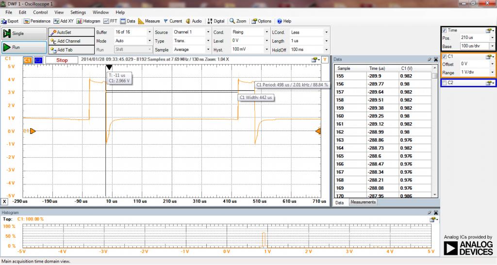
(picture of the signal going to the motor of a Lady Bird quad)
I tried using this set-up and out putting a 4kHz PWM to a transistor (2N2222A or a 2N3904) like this:
http://www.robotroom.com/PWM5.html
I think Im missing something because Im pretty sure that Im using the above set-up, but its not working. You can see in the picture that the output wave and the wave taken from the motor leads are very different.
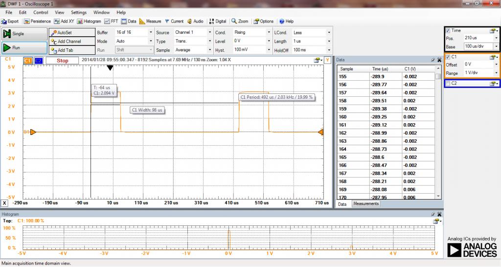
Wave output from the propeller only
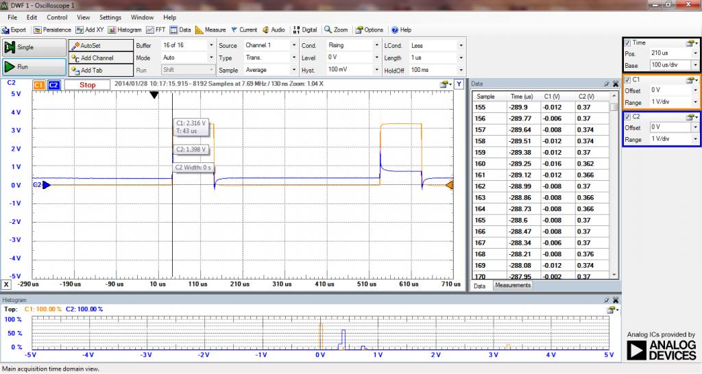
Wave output from the propeller and wave form taken from the motor leads
Set-up: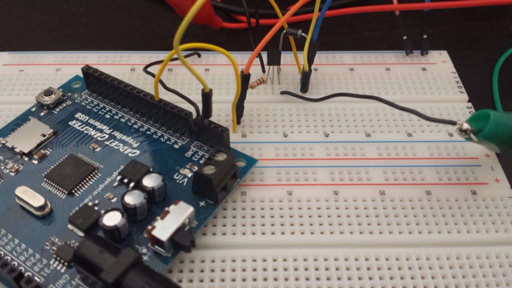
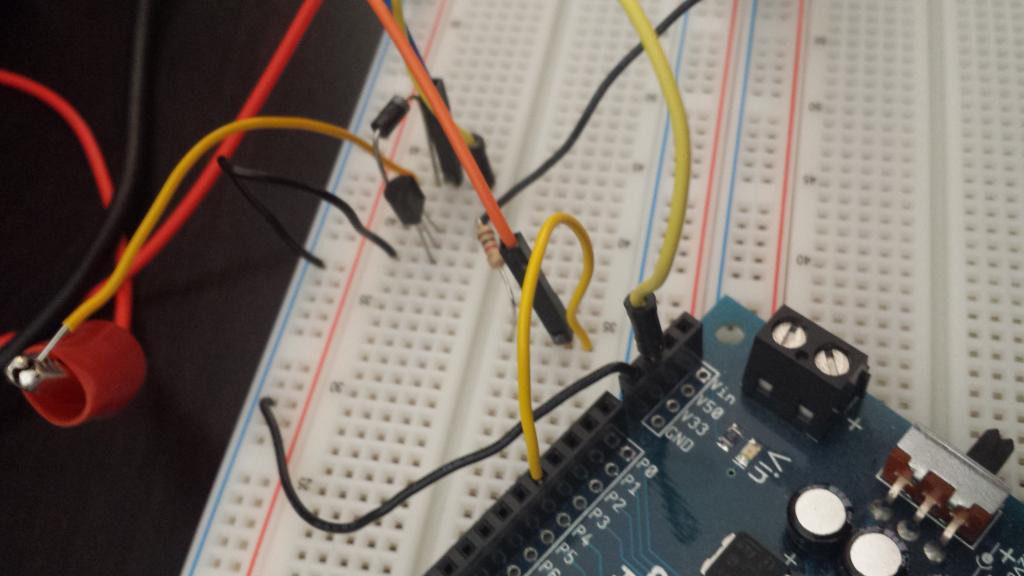
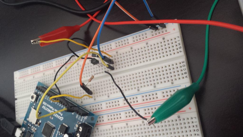
This is new to me so any suggestions? Ive tried replacing the 2N2222A with a 2N3904, but the wave forms are the same.
Below is the code that Im using its from Beau's PWM Demo Object, but I think it's an electrical problem.
http://www.hobbyking.com/hobbyking/store/__24746__Motor_w_Mount_and_Boom_Complete_counter_clockwise_rotation_QR_Ladybird_Micro_Quad.html
Im pretty sure that they require a PWM with a specific frequency like 4kHz, then you just change the duty of the wave to increase or decrease the speed of the motor.

(picture of the signal going to the motor of a Lady Bird quad)
I tried using this set-up and out putting a 4kHz PWM to a transistor (2N2222A or a 2N3904) like this:
http://www.robotroom.com/PWM5.html
I think Im missing something because Im pretty sure that Im using the above set-up, but its not working.

Wave output from the propeller only

Wave output from the propeller and wave form taken from the motor leads
Set-up:


This is new to me so any suggestions? Ive tried replacing the 2N2222A with a 2N3904, but the wave forms are the same.
Below is the code that Im using its from Beau's PWM Demo Object, but I think it's an electrical problem.
{{
''*******************************************
''*  PWM DEMO Object                   V1.1 *
''*  Author: Beau Schwabe                   *
''*  Copyright (c) 2009 Parallax, Inc.      *
''*  See end of file for terms of use.      *
''*******************************************

Revision History:
  Version 1.0   - (05/01/2009) initial release
  Version 1.1   - (05/11/2011) edited some of the descriptive text

}}
CON
  _CLKMODE = XTAL1 + PLL16X
  _XINFREQ = 5_000_000

OBJ     PWM     : "PWM_32_v4.spin"

PUB DEMO_Example | DutyCycle
''-------- This Block Starts the PWM Object ----------
    PWM.Start                   '' Initialize PWM cog


''-------- This Block sets a Standard servo on Pin 0 to it's center Position ----------
    PWM.Servo(0,1500)           '' Define Pin0 with a standard center position        '0
                                '' servo signal ; 1500 = 1.5ms

                                 ' Most servo's will accept a value ranging from 1ms to 2ms
                                 ' Parallax servos will operate from 0.5ms to 2.5ms ... or 500us to 2500us

                                 ' The Width of this pulse determines the servo's position with 1500 positioned
                                 ' at center.  The pulse to the servo's must be repeated at a rate of 50 times
                                 ' per second.  The PWM.Servo takes care of this for you where all you need to
                                 ' do is set it and forget it and it will keep generating the signal for you.


''-------- This Block creates a 3-Phase 60Hz square wave on Pins 1,2, and 3 -----------
    PWM.Duty(4,20,500)        ''Create a 60Hz 50% duty cycle on Pin1      16666           32Khz= 31.25            8Khz = 250   2kHz = 500
   ' PWM.Duty(2,50,16666)        ''Create a 60Hz 50% duty cycle on Pin2
   ' PWM.Duty(3,50,16666)        ''Create a 60Hz 50% duty cycle on Pin3

