Shop OBEX P1 Docs P2 Docs Learn Events
LED extender question — Parallax Forums

LED extender question

john_sjohn_s Posts: 369
edited 2014-01-29 11:44 in General Discussion
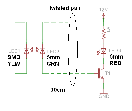
I need to "move" (extend / expand?) the smd LED1 hidden inside the box so it can be visible from a front panel.
I planned to use a fiber-optic pipe glued to LED1 but decided otherwise due to several other factors.

So here's my idea of doing it using a minimum number of components. Any comments?
LED-to-LED.PNG


Correction: it should rather be LED3 moved away from all other circuitry by 30cm.
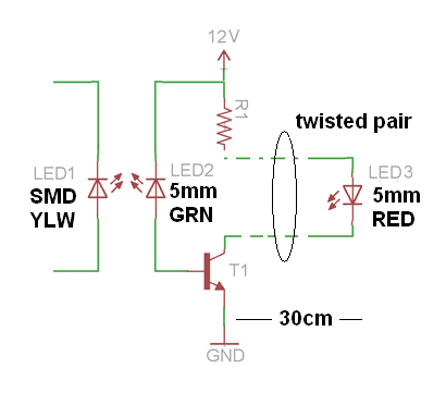
LED-2-LED.PNG
446 x 375 - 16K
410 x 383 - 15K

Comments

  • ercoerco Posts: 20,259
    edited 2014-01-27 13:24
    Do you intend to make an optoisolator using a 5mm green LED as a light sensor to detect light from the SMD yellow LED? Is that sensitive enough? Why not replace the SMD yellow with a real optoisolator? Or while you're in there, just remove the SMD yellow and solder wires on to run out to your LED indicator. That's the minimum part solution, zero.

    Alternatively, use a phototransistor to pick up the yellow LED output. Heck, you could even kick it old school with a non-RoHS cadmium photocell, which is coincidentally most resposive to yellow-green light.
  • Peter JakackiPeter Jakacki Posts: 10,193
    edited 2014-01-27 13:35
    john_s wrote: »
    I need to "move" (extend / expand?) the smd LED1 hidden inside the box so it can be visible from a front panel.
    I planned to use a fiber-optic pipe glued to LED1 but decided otherwise due to several other factors.

    So here's my idea of doing it using a minimum number of components. Any comments?
    LED-to-LED.PNG


    Correction: it should rather be LED3 moved away from all other circuitry by 30cm.

    LED-2-LED.PNG

    Why wouldn't you just extend the LED with a cable, nothing else. I don't get what you are trying to do with this arrangement here though and why different color LEDs? I have used LEDs as photodetectors (reverse current or forward voltage) but this arrangement here is far from it.

    BTW, the plastic tube that can be used to pipe the light is not fiber-optic at all, it's just a light pipe.
  • RDL2004RDL2004 Posts: 2,554
    edited 2014-01-27 13:57
    I'm guessing the OP doesn't want to modify or risk damaging the board, or maybe would just rather not deal with smd soldering. I'd probably just try to use a phototransistor.
  • Peter JakackiPeter Jakacki Posts: 10,193
    edited 2014-01-27 14:18
    RDL2004 wrote: »
    I'm guessing the OP doesn't want to modify or risk damaging the board, or maybe would just rather not deal with smd soldering. I'd probably just try to use a phototransistor.

    I know, but I that +12V has to come from somewhere too. The different color LEDs just didn't make sense, I'm sure that an LED is most sensitive to light of the same wavelength as it. Also the minute reverse current through the receiver LED might just work if you had a very bright light but very unlikely with the source specified. The transistor is not even biased either but is better off being replaced with a comparator or opamp, then it would have a chance.
  • tonyp12tonyp12 Posts: 1,951
    edited 2014-01-27 15:42
    If the board is what it is, when find the spot before the smt resistor that goes to the SMT led and put external LED lead there with it's own resistor in series.
    Now both LEDs will come on
  • Phil Pilgrim (PhiPi)Phil Pilgrim (PhiPi) Posts: 23,514
    edited 2014-01-27 16:49
    I'd go with a photo-Darlington. You will probably need the extra gain if the SMD LED isn't extremely bright.


    -Phil
  • ercoerco Posts: 20,259
    edited 2014-01-27 16:57
    I'd go with a photo-Darlington. You will probably need the extra gain if the SMD LED isn't extremely bright.

    Oh great one of all things opto-technical: have you ever used a Light-activated SCR? From what I understand they used to be popular in slave photoflash units. Exceptionally rare & hard to find these days, especially at the price I want to pay. :)
  • john_sjohn_s Posts: 369
    edited 2014-01-27 17:56
    I'd go with a photo-Darlington. You will probably need the extra gain if the SMD LED isn't extremely bright.


    -Phil

    That T1 was supposed to be a Darlington... :)
    Now, photo-Darlington is what I need for sure!

    The whole idea is to make minimum (read:zero) modification to the pcb that has that yellow LED1, yet to extend LED1's visibility range to exhibit its"brightness" a short distance away.
    Hence the contraption emulating light pipe. Also, there is 12V available so no problem with powering it.
  • john_sjohn_s Posts: 369
    edited 2014-01-27 17:58
    erco wrote: »
    Do you intend to make an optoisolator using a 5mm green LED as a light sensor to detect light from the SMD yellow LED?.

    That is exactly my objective.
  • Peter JakackiPeter Jakacki Posts: 10,193
    edited 2014-01-27 19:04
    john_s wrote: »
    That T1 was supposed to be a Darlington... :)
    Now, photo-Darlington is what I need for sure!

    The whole idea is to make minimum (read:zero) modification to the pcb that has that yellow LED1, yet to extend LED1's visibility range to exhibit its"brightness" a short distance away.
    Hence the contraption emulating light pipe. Also, there is 12V available so no problem with powering it.

    You could have a darlington then but that requires at least 1.2V Vbe threshold before it even starts to think about conducting. A photodarlington is more realistic though but still, I would just solder to the pcb. Why can't you do that?
  • john_sjohn_s Posts: 369
    edited 2014-01-27 19:27
    ... I would just solder to the pcb. Why can't you do that?

    Unfortunately I cannot solder anything to that proprietary pcb hence all that gymnastics to accomplish it kinda "remotely"
  • Phil Pilgrim (PhiPi)Phil Pilgrim (PhiPi) Posts: 23,514
    edited 2014-01-27 21:00
    Here's the circuit I had in mind:

    attachment.php?attachmentid=106526&d=1390885181

    The two transistors are actually a single, integrated photo-Darlington.*

    -Phil

    Update: * Well, maybe not. DigiKey's selection of photo-Darlingtons seems to be limited to IR-sensitive types.
    327 x 334 - 2K
  • john_sjohn_s Posts: 369
    edited 2014-01-27 22:25
    Yeah, that's the one - time to find a photo-Darlington that does the job and is not IR limited like http://media.digikey.com/pdf/Data%20Sheets/Fairchild%20PDFs/L14F1,%20L14F2.pdf

    Or perhaps a "pair" of visible light PIN diode + 2N3904?
    http://www.digikey.ca/product-highlights/us/en/vishay-tefd4300-pin-photodiodes/1248
  • Beau SchwabeBeau Schwabe Posts: 6,568
    edited 2014-01-27 22:47
    I'm still a little concerned that the transistors will not be biased correctly, even in the darlington configuration.

    While this circuit is designed for an AC signal (or fluctuating signal) , it might be ok if you are just wanting a visual indicator effect.
    http://forums.parallax.com/showthread.php/149216-DEMO-IR-Heartbeat-detector

    In the circuit above the IR receiver is reverse biased in a way very similar to your first post. The two NPN transistors form an auto biasing circuit.
    I'd have to R&D the circuit a little bit for the best configuration for driving an LED but it shouldn't be too painful.
  • john_sjohn_s Posts: 369
    edited 2014-01-27 23:12
    I'd have to R&D the circuit a little bit for the best configuration for driving an LED but it shouldn't be too painful.

    Thanks Beau - I'll be waiting for the results!
  • john_sjohn_s Posts: 369
    edited 2014-01-28 09:08
    I figure that we're after something similar to this http://www.epanorama.net/circuits/irdetector.html (elegant and simple but minus IR)
  • Beau SchwabeBeau Schwabe Posts: 6,568
    edited 2014-01-28 13:43
    The circuit for the IR heartbeat detector will work.... Remove the 10uF, 2.2k, 1k, and 0.047uF Cap ... Connect the Anode of your indicator LED (red) to the collector of the right most 2n3904 transistor. Connect the Cathode to Gnd or Vss.

    Note: Circuit is very sensitive... reduce value of 1Meg resistor to de-sensitize


    Reference: IR LED used for test.
    http://www.ebay.com/itm/10Pcs-5mm-940nm-IR-infrared-Receiving-LED-Lamp-/140909599066?pt=LH_DefaultDomain_0&hash=item20ceddd95a
  • john_sjohn_s Posts: 369
    edited 2014-01-28 14:19
    Ready to test it - thanks Beau!
  • john_sjohn_s Posts: 369
    edited 2014-01-28 20:56
    Test results on modified circuit powered from 9V battery did not produce expected results...
    The circuit works lovely as an IR pulse detector with one-shot trigger characteristic and LED blinking upon receiving IR-pulses from any tv remote control.
    However, when placed near powered up LED of any colour it does not detect it at all. Not even a single blink.

    I suspect that it has to do something with my BPW-41 IR PIN diode that cannot see single spec wavelength of LED.
    I tried another model (Telefunken and Siemens) and still no cigar.
    Although it works just fine as an incandescent or plain bulb light detector.

    Beau - did I miss something when modifying your schematic?
    IRHEART_m.PNG
    650 x 481 - 109K
  • Phil Pilgrim (PhiPi)Phil Pilgrim (PhiPi) Posts: 23,514
    edited 2014-01-28 21:07
    If the PIN diode is designed to be sensitive to IR, it will not respond to a green LED, which puts out no infrared. The reason it responds to incandescent light is that it's rich in IR.

    -Phil
  • john_sjohn_s Posts: 369
    edited 2014-01-28 21:25
    If the PIN diode is designed to be sensitive to IR, it will not respond to a green LED, which puts out no infrared. The reason it responds to incandescent light is that it's rich in IR.

    -Phil

    I also tried the reversed biased LED to act as the front end detector for the matching colour xmtr but with the same negative results.
  • Phil Pilgrim (PhiPi)Phil Pilgrim (PhiPi) Posts: 23,514
    edited 2014-01-28 21:29
    I tried my circuit above (post #14) both with a photoransistor and with a photodarlington placed over a green SMD LED. Each works fine, with the darlington being the more sensitive.

    -Phil
  • ercoerco Posts: 20,259
    edited 2014-01-28 21:32
    Once again, if you're dead set on using the light off a yellow LED, an old school photocell is most sensitive to yellow-green light. Worst case, you have to make a comparator circuit to switch on your remote LED.
  • Peter JakackiPeter Jakacki Posts: 10,193
    edited 2014-01-29 04:27
    john_s wrote: »
    Test results on modified circuit powered from 9V battery did not produce expected results...
    The circuit works lovely as an IR pulse detector with one-shot trigger characteristic and LED blinking upon receiving IR-pulses from any tv remote control.
    However, when placed near powered up LED of any colour it does not detect it at all. Not even a single blink.

    I suspect that it has to do something with my BPW-41 IR PIN diode that cannot see single spec wavelength of LED.
    I tried another model (Telefunken and Siemens) and still no cigar.
    Although it works just fine as an incandescent or plain bulb light detector.

    Beau - did I miss something when modifying your schematic?
    IRHEART_m.PNG

    I've always used LEDs as photodetectors in the photovoltaic mode, never in reverse. The LED's cathode is grounded and the anode is fed directly into the base of a transistor although it could be a darlington though I've never tried it.
  • john_sjohn_s Posts: 369
    edited 2014-01-29 11:23
    I tried my circuit above (post #14) both with a photoransistor and with a photodarlington placed over a green SMD LED. Each works fine, with the darlington being the more sensitive.

    -Phil

    Yeah, the same here - but I sort of focused on Beau's circuit :)
    The Darlington circuit was also too sensitive as I need an ON/OFF only.
  • Beau SchwabeBeau Schwabe Posts: 6,568
    edited 2014-01-29 11:44
    "Beau - did I miss something when modifying your schematic?" - No, that's it.... The transistors in that configuration create an auto-biasing circuit. Another common biasing circuit is just to tie the base of a transistor to V+ through a current limiting transistor so that the transistor 'just' turns on. This works but it won't be as sensitive and it won't be able to track changes in light intensity. The circuit should also work by replacing the IR detector with an LED (also in reverse bias). If your detecting Yellow, then I would use a Yellow LED for the sensor, but also make sure the the detector LED is in a "clear" package. If the circuit is NOT sensitive enough, then increase the 1Meg to a 10 Meg... likewise, if it is too sensitive, decrease the 1Meg to de-sensitize the circuit.
Sign In or Register to comment.