handling propeller on an unknown board
hello everyone,
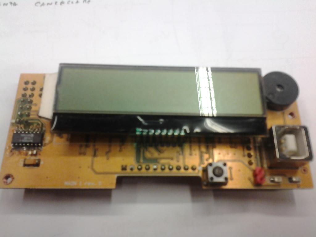
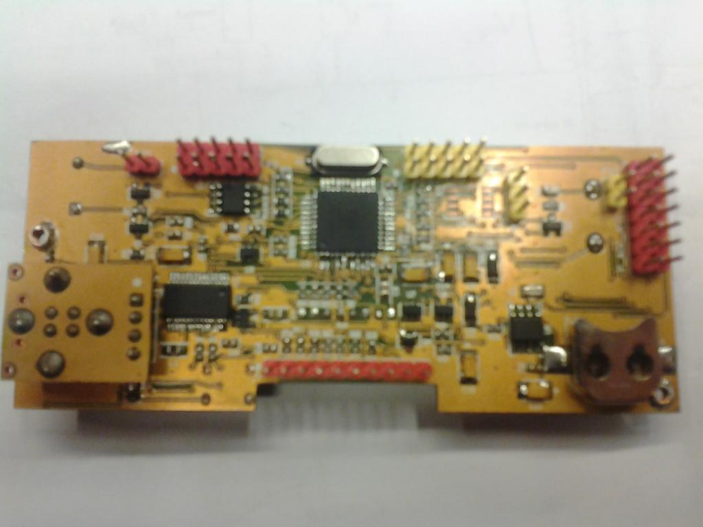
I'm stuck with this system, a Propeller on a board I don't recognize (pictures enclosed) that manages actuators in a black box.
I've removed cables for the pictures; there are some (long thin red down horizontal) connecting to a button panel and others that go to the "black box of actuators".
On the board I recognize the MCP3208-C ADC, the FT232RL USB2UART, then there's a buzzer, a usb plug, a batter case (w/out battery), a reset button and an LCD panel soldered to the board
.
I've been over soooo many pics in the web looking for this board, since I'd like schematics to see where pins are, but I haven't been able to find what I was looking for.
I know it's a long shot but...maybe some of you guys knows this one.
tnx!
Giovanni


Comments
what makes you sure that it is a propeller-chip?
The pictures are a bit out of focus.
best regards
Stefan
It sure looks like a custom board to me. I haven't seen one like it before.
Doesn't look like any board that anyone on the forum did. The closest would be Ray, given that it's got a display on it.
A better photo would be in order.
No enhancing. I'm sure I can see a beanie on the chip. I can also see where "Parallax" is written but I can't read it on the chip.
I have two monitors and I can only see the beanie on one of them. It's very faint but it is there.
There are real questions of ethics and courtesy toward the originator if you desire to reverse engineer it. As owner of the board, I figure that you are welcome to hack all you want. But as part of the Parallax forum community, we should respect builders that want to keep their designs to themselves and sell an end product.
This could be a proto-type that never reached the marketplace. I must admit that if it is a Propeller-driven device, it is loaded with a lot of nice features and worth reverse-engineering to redeploy.
Can you have software recognize a Propeller for programing purposes? It would be rather easy to trace Pins 31 and 30 to see if they are active. If not, the board is setup to be used with a pre-written EEPROM and not intended to be hacked.
I have not seen this anywhere on the net either, and a short while back, I did a pretty intense search for Propeller Boards to make a full list. I would also guess that it is a custom design for a specific project that was probably designed by someone familiar with the Propeller, but not publicized for it being proprietary or something.
What's the need for knowing it better? Is it not woking properly or do you need to make additional units or do you just have it to do as you please with it? It probably wouldn't be too hard to reverse engineer the design.
I used my wife's computer (since she has PhotoShop on it) to see if I could enhance the beanie.
This is the best I could do at enhancing the beanie with my limited PhotoShop skills.
I did not change the orientation of the photo. The top of the beanie is pointing to the left.
Now someone tell the guys in the white coats standing at my door to go away.
It certainly gets rid of the noise and out of focus problems. Maybe the original poster could do the same so that we can get a better view of the chip in question.
I presume you cannot find out who the board/box was purchased from?
Is the board faulty?
I am uncomfortable and therefore cannot help to reverse engineer someone's commercial product.
BTW It's not one of my boards.
now. The board is part of a project I'm taking over. I don't think it was /developed/ but rather bought and made it fit in the project. I just don't have the necessary documentation useful to write programs with this hardware, in that I wouldn't know were -say- P12 (*) is connected to. I could debug it (already on it) but it takes time and wouldn't be as comprehensive as a full schematics of the board.
(*) references on the board seem to point to several pins using the same name: e.g. P9 points to three pins and P8 to ten -> it actually point to several buttons on the board (there are NINE of them)
I include better pics this time (the chip is the P8X32A-M44 44-pin as you can see). Please understand I'm not trying to steal anybody's work, just trying to make a machine work w/ a new configuration.
Giovanni
If Pin 31 and P30, and the Reset are wired in standard configuration to a USB port... you should be able to download a binary image of the EEPROM via the Propeller Tool IDE.
That would allow two things.
A, You would have a back up image of the existing EEPROM.
B. You could, after reparsing the 8 bit data into 32bits, attempt to reverese engineer the code within the EEPROM.
It looks as though you have a lot of other chips on the board that have to be tracked to Pins 0 through 27. But if you can't get an image of the existing binary, you will have much less indication of what the original software was attepting to do. Of course, there is no way to know that the software was any good in the first place.
The other chips will give you some indication of what kind of code the Propeller is involved with -- asychronous serial, various synchronous serial, and parallel. After identifyng what provides communications and display services; the rest is the meat and bones of the device's actual task deployment.
~~~~~~~~~~~
So, download the Propeller Tool IDE.
Then familiarize yourself with offloading a Propeller binary image from EEPROM. I would practice on a second Propeller board if I was unsure of what I needed to do.
Then, the binary data might best be manipulated in Linux as there are a lot of Unix legacy tools to do these kind of things... they are good and they are free.
I have the eeprom file in my hands. I've tried deassemble-tools such as GEAR, but the output really does not make much of a sense (to me). Therefore I'm rewriting it all (they say it's bound to be better, the second time - they say). That's why I would like to know which is which, I mean how are the pins labelled/where are they.
I know some, of what the code is supposed to do (it reads values, compares them, eventually performs operations on the output pins), but still I don't know how this is really going to be useful to me. I wish I could follow the trails on the card.
I only know that I have to "get dirt" and touch and move and try many things. The only way out is through.
The binary has to be searched against a complete list of Propeller machine code. It is either PASM entirely or a mix of Pasm and Spin.
This is not an easy first Propeller project.
I don't know what GEAR is, and SPIN adds an additional issue to sort out.