Shop OBEX P1 Docs P2 Docs Learn Events
Regarding LM317: Not getting required output — Parallax Forums

Regarding LM317: Not getting required output

sachin25febsachin25feb Posts: 5
edited 2014-01-18 22:34 in General Discussion
Dear All,
I am working on failure analysis of products.
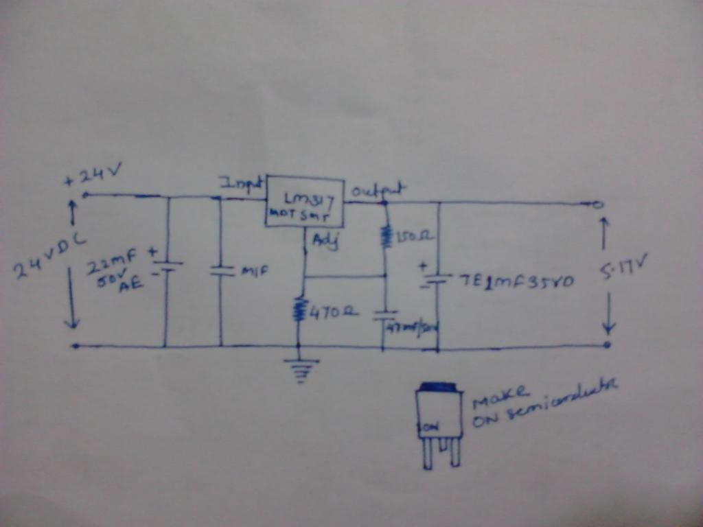
In one faulty module we use LM317 for 5.17 V generation.
The reported problem is that the output voltage is not observed and sometimes it is observed (During vibration)
After analysis it is observed output pin of LM317 is not soldered so sometimes it is get connected and sometimes it is not.
But problem is that when output pin is firm with soldering pad that time at the output voltage observed 10.48V instead of 5.17V.
When output not observed that time output voltage is occurred 0.25V.

When I soldered output pin then everything is working fine and observed 5.17 v exact.

Now i want to know why this happen in that instance I got sometime 10.48 V and sometime 0.25V.

I attached herewith snap of circuit.
Please help me friends it is very interesting problem.
your suggestions and comments regarding this problem is must.
1024 x 768 - 33K

Comments

  • LeonLeon Posts: 7,620
    edited 2014-01-17 08:57
    It might be oscillating, if the load isn't connected. The capacitor on the output should be close to the regulator pins, with short connections.
  • sachin25febsachin25feb Posts: 5
    edited 2014-01-17 08:58
    Will you more elaborate please
  • Mike GreenMike Green Posts: 23,101
    edited 2014-01-17 09:13
    Regulators are high gain sensitive amplifiers. To stabilize them, you have to use a capacitor across the output leads and usually another capacitor across the input leads. For most regulators, the value of the capacitor and its ESR is very important and is spelled out in the datasheet for the regulator. These capacitors should be mounted close to the regulator to minimize the impedance of the connecting wires. If you don't do this properly, the regulator may oscillate causing a significant variation in the output voltage over time.
  • RDL2004RDL2004 Posts: 2,554
    edited 2014-01-17 18:24
    It may have nothing to do with your problem, but 24 volts is way too much input voltage for only 5 volts out unless you barely draw any current at all.
  • sachin25febsachin25feb Posts: 5
    edited 2014-01-17 20:09
    Mike Green wrote: »
    Regulators are high gain sensitive amplifiers. To stabilize them, you have to use a capacitor across the output leads and usually another capacitor across the input leads. For most regulators, the value of the capacitor and its ESR is very important and is spelled out in the datasheet for the regulator. These capacitors should be mounted close to the regulator to minimize the impedance of the connecting wires. If you don't do this properly, the regulator may oscillate causing a significant variation in the output voltage over time.

    Thanks for your prompt reply.
    please see attached pic it gives you exact idea about components position on PCB please comment on it
    1024 x 768 - 37K
  • bluejaybluejay Posts: 131
    edited 2014-01-17 21:30
    Why is this posting on Basic Stamp Forum instead of General Forum?
  • davejamesdavejames Posts: 4,047
    edited 2014-01-17 21:43
    bluejay wrote: »
    Why is this posting on Basic Stamp Forum instead of General Forum?


    ...good question!

    Thread moved to General.
  • LoopyBytelooseLoopyByteloose Posts: 12,537
    edited 2014-01-17 21:54
    The likely short story is this...

    A soldered connection is reliably low resistance connection.
    A breadboard insertion is a variable higher resistance connection.

    You can only do so much on a breadboard to test a concept. It is never a reliable durable solution, especially for power distribution. The contacts get dirty, become looser with age, and so on. The size of the wires you use with a breadboard varies from person to person, so how snug your fit is depends on your awareness of wire size and the 'snugness' of the insertion.

    In other words, breadboards misbehave.
  • sachin25febsachin25feb Posts: 5
    edited 2014-01-17 22:04
    The likely short story is this...

    A soldered connection is reliably low resistance connection.
    A breadboard insertion is a variable higher resistance connection.

    You can only do so much on a breadboard to test a concept. It is never a reliable durable solution, especially for power distribution. The contacts get dirty, become looser with age, and so on. The size of the wires you use with a breadboard varies from person to person, so how snug your fit is depends on your awareness of wire size and the 'snugness' of the insertion.

    In other words, breadboards misbehave.

    Dear Friend,

    The ckt not made on breadboard it is proper designed on two layer PCB board. For your reference please find attached Assembly diagram
    1024 x 768 - 37K
  • kwinnkwinn Posts: 8,697
    edited 2014-01-17 22:42
    Based on your statement "When I soldered output pin then everything is working fine and observed 5.17 v exact." I would guess that it was a cold solder joint That would appear as a blob of rough grayish solder covering the pin and pad rather than a smooth joint that resembles a mini volcano with the lead in the center. I've seen hundreds, possibly thousands of them over the years. Very common when boards are hand soldered by unskilled people.
  • LoopyBytelooseLoopyByteloose Posts: 12,537
    edited 2014-01-17 23:27
    Forgive me for presuming a breadboard construction....

    That comment "When I soldered...." got me to thinking you started with a breadboard, and switched. I realize that English is not your 1st language, it just was a bit unclear what you had stated with.

    A Cold-solder joint is yet another variable high-resistance connection. These do happen more often that we would like to see.

    When I build a board, I test the voltage output with the regulator in place... but other components that might suffer from an over-voltage not yet installed.

    Quite often, my attempts at construction either present an over-voltage from some error in construction. Or the regulator is over-heating from a direct short caused by a solder bridge. This has happened so often that I keep one finger on the regulator when I power up ... just to monitor the heat and to allow me to quickly disconnect power.

    These are just the hazards of small production runs with manually soldered components.

    In general, a cold-solder joint looks ugly; a good one is nice and tidy. So when in doubt, re-heat the ugly ones until they look good.

    Feedback from the output pin helps to determine the output... so unstable resistances cause unusual output.
  • sachin25febsachin25feb Posts: 5
    edited 2014-01-18 22:34
    Forgive me for presuming a breadboard construction....

    That comment "When I soldered...." got me to thinking you started with a breadboard, and switched. I realize that English is not your 1st language, it just was a bit unclear what you had stated with.

    A Cold-solder joint is yet another variable high-resistance connection. These do happen more often that we would like to see.

    When I build a board, I test the voltage output with the regulator in place... but other components that might suffer from an over-voltage not yet installed.

    Quite often, my attempts at construction either present an over-voltage from some error in construction. Or the regulator is over-heating from a direct short caused by a solder bridge. This has happened so often that I keep one finger on the regulator when I power up ... just to monitor the heat and to allow me to quickly disconnect power.

    These are just the hazards of small production runs with manually soldered components.

    In general, a cold-solder joint looks ugly; a good one is nice and tidy. So when in doubt, re-heat the ugly ones until they look good.

    Feedback from the output pin helps to determine the output... so unstable resistances cause unusual output.
    Thanks for your valuable thinking
Sign In or Register to comment.