

TX / RX Activity Light Circuit
 photomankc
Posts: 943
photomankc
Posts: 943
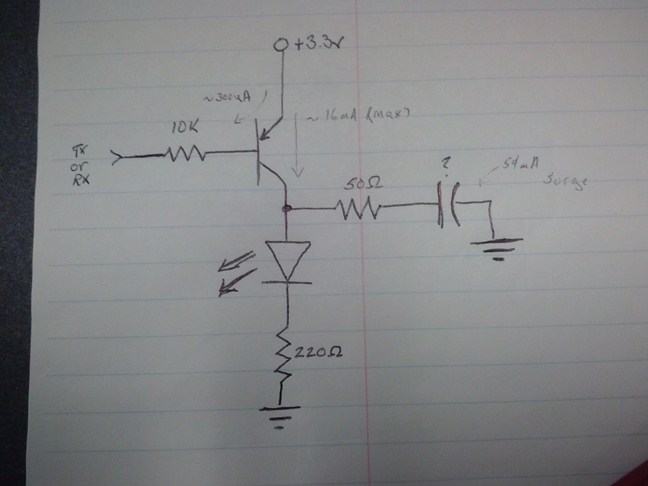
Trying to work out a simple LED indicator scheme for UART lines and wanted to know if this seemed appropriate. Most of my connections are well above 9600 bps often at 115300 bps. With such rates the LED would only be activated for something like 8 microseconds. My idea was to put a low value cap beyond the transistor to try to extend the LED on period a bit. I have not worked out all the math yet but I'm thinking this creates a short blank period as the cap charges up and then the LED should light and when the transistor turns off then the cap keeps the LED lit and dimming till it crosses the threshold voltage. I'm betting the challenge is finding a cap value that is significant enough to actually add any perceptible time to the LED on period without taking so long to charge the cap that there is no benefit.
Anything obviously brain dead in this?
Anything obviously brain dead in this?
648 x 486 - 46K
Comments
PS - is this for 3.3V level serial data?
I just did a couple of tests using a Prop with a baud rate of 115200.
I assume the TX and RX are normally high when no data is being transferred.
Is this true?
Of course the resistor in series with the cap is not needed, it even gets in the way of charging the cap.
The problem is, one needs at least 10uF and preferably 100uF to get a reasonably long flash on the LED because the charge in the cap is powering the LED.
Your simple 1 transistor circuit just can't charge the relativly large cap rapidly enough to catch a single character let alone a single start bit.
Questions about circuit requirements.
1. Can I use 2 transistors and a few resistors?
or
2. Can I use a small MOSFET? Say a 2N7000? Or a junction FET?
I have a plan but didn't get it running yet. Will work on it after dinner.
Duane J
I just tested many variations of kwinn's circuit.
However, there are some differences in component values.
I did my testing using FemtoBasic using this program: And the interface to my PC is a USB PropPlug.
I see there are some basic requirements:
1. The circuit must not interfere with normal operation of the serial port.
2. I usually run at 115200 baud.
3. I want to at least be able to see the LED flash with the worst case character. In this case sending 8 1's. So one sees only the start bit. Of course the LED is brighter with characters that have more 0's.
1. The gain of my 2N3906 PNP transistors is about 180. With a base resistor of 10KΩ the current through the LED is self limited so the 330Ω resistor is not required. Better yet any color LED from RED to BLUE work equally well.
2. The start bit is about 9uS wide. If the capacitor is to large it affects the fall time which may cause bit errors. I find that 10nF is about right.
If you want to operate at a slower bit rate the capacitor can be proportionately larger.
3. There is no need for the 100Ω input resistor. In fact it just limits the charge on the capacitor dimming the LED no mater what value I tried.
So my conclusion is to just use the 4 parts:
2N3906, 10nF, 10KΩ, and the 1N4148 signal diode.
Have fun with this.
Thank you kwinn for the nice circuit!!!
Duane J
Why wouldn't you do this in software? I don't think I've ever bothered to create a one-shot just for activity leds when it is very easy for software to light em up and reload a timer. Somewhere in your code, either in the main loop or polling etc you check for a timeout and turn them off, simple.
Excellent, thank you guys. I was busy helping my daughter solder up her line-follower kit tonight so I didn't have time to test anything at the bench. That's a nice solution.
Peter, I have a couple of LEDs tied to GPIO for software to wiggle however id still have 3 other UARTs to cover and don't want to spend 3/6 more GPIO for the task. I may not have room to place that many components either but I wanted something that would work even where I don't have a uC at hand. This may be perfect for activity lights on my cheap sonar sensors too when I build that interface board
I added a version using a P-Chanel Junction FET, J176, which works better, i.e. brighter with the 9uS pulse.
In the JFET circuit a bit of description is needed.
Since a junction FET's gate can conduct if forward biased I added the 10KΩ resistor to limit this current flow.
If I had used a small low gate voltage MOSFET that resistor would not be needed, I don't have one on hand.
An even better MOSFET would be a small low gate voltage Depletion Mode MOSFET, alas I don't have one of these either.
Notice, I show a second diode so one could watch both TX and RX with one circuit.
Saves some board space too.
A bunch of diodes would allow us to watch many signal lines at the same time.
Stretching a 9uS pulse out enough to be visible on an LED ain't half bad for such a simple circuit!!!
BTW, this "Pulse Stretcher" can be useful in many application.
Duane J
Always happy to help out.
Just flip the PNP circut up side down and use a 2N3904.
And reverse the diodes.
I just tried it and works fine. (No time to try the JFET circut though.)
Duane J
One hardly ever sees JFETs in digital applications. They are well suited to analog amplifiers and current sources because of their inherent "Depletion Mode" characteristics. I.e. when the gate is at the same voltage as the source it conducts current. However, usually one doesn't want to forward bias the gate junction but not illegal to do so within reason.
I suspect because of this pesky gate PN junction JFETs are not more prominently used. In the early days there were high powered JFETs.
Of course, now MOSFETs have largely supplanted JFETs, but MOSFETs are mostly "Enhancement Mode" types.
"Depletion Mode" MOSFETs have all the attributes of JFETs without the PN junction gate. Way cool. Not may make them though.
Duane J
I have tried your Jfet model for Rx/TX activity. Led is not brighter?? do you have any suggestions??