Active Low Chip Select With Assembly Routine
I'm trying to make an assembly based serial (SPI master) routine. My device has standart chip-select, clock and data signals. But chip-select is Active Low.
I'm confused with how to handle output direction and status of CS signal between main program (SPIN) and my assembly routine.

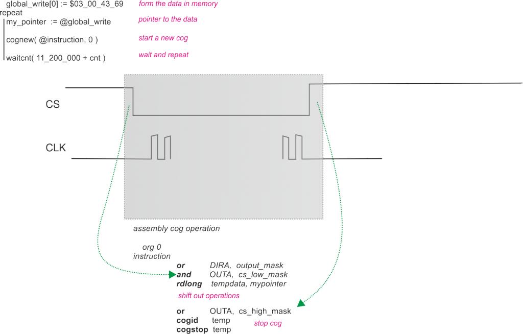
I tried to draw what I'm trying to do. In my main program, I put 32bit data into a variable and start a new cog for my assembly routine. In the ASM, I generate a clock signal. Shift out and shift in data using IO pins. It is really fast and I liked it. When I probe the signals with oscilloscope, everything seems fine except the CS signal. It creates only a very short duration HIGH pulse.
Should I define CS signal in main program (SPIN) as output as well? What should be the DIRA and OUTA status in main program? Briefly, how can I make CS low only in the ASM routine and let it remain HIGH outside ASM routine? I also tried to control CS pin at the SPIN side before and after COG operation but it became much much slower than my shift IN/OUT operations.
I know outputs are ORed in the P.Propeller. So, it would be really easy to do this if the CS would be an active HIGH signal.
I found some SPI assembly objects on OBEX but I want to write my own rouine and frankly, I want to understand why this is not working.
Thank you
I'm confused with how to handle output direction and status of CS signal between main program (SPIN) and my assembly routine.

I tried to draw what I'm trying to do. In my main program, I put 32bit data into a variable and start a new cog for my assembly routine. In the ASM, I generate a clock signal. Shift out and shift in data using IO pins. It is really fast and I liked it. When I probe the signals with oscilloscope, everything seems fine except the CS signal. It creates only a very short duration HIGH pulse.
Should I define CS signal in main program (SPIN) as output as well? What should be the DIRA and OUTA status in main program? Briefly, how can I make CS low only in the ASM routine and let it remain HIGH outside ASM routine? I also tried to control CS pin at the SPIN side before and after COG operation but it became much much slower than my shift IN/OUT operations.
I know outputs are ORed in the P.Propeller. So, it would be really easy to do this if the CS would be an active HIGH signal.
I found some SPI assembly objects on OBEX but I want to write my own rouine and frankly, I want to understand why this is not working.
Thank you


Comments
BTW, are you aware of the ANDN instruction? It works like AND but uses the inverted value of your mask. Assuming pin has been made an output, you can set it high (disable) with OR, and take it low (enable) with ANDN -- using the same mask.
Edit: Looking more closely at your diagram, if you're stopping the cog that controls the CS pin, you should pull that pin high through a resistor so that the device is deselected after you stop the cog.
If you want to create a SPI Master that is written in pasm (in a new cog of course)
1: Spin sets up a buffer variable (data) plus a flag variable that you should put before the buffer space,
so the pasm cogs know when new data is there and clear it when done.
2: Start the pasm cog with cognew pointing to the flag variable, the cog will use PAR for this address.
3: cog sets up DIRA and OUTA, as each cog must sets it's own.
3: run a loop rdlong t1,PAR wz ; get 1 as ready or use length-of-data if variable lengths happens
if_z jmp #3
4 : andn CSpin
5: mov t2,PAR
6: add t2,#4
7: rdlong t3,t2
8: rol t3(data),muxc pin, or & andn clock pin.
innerloop
9: or CSpin
10: jmp to 3
1. drivers usually drive I/O pins and this is much easier with the COG staying alive as you already found out. Otherwise you need synchronization with another COG that takes over the I/Os - or use external resistors which keep them in a defined state - like Jonny said.
2. starting a COG always needs some time which reduces the response time to your task that wants to send something via SPI.
The nice thing with this kind of background waiting COG is that you can create a basic skeleton (like sketched by Tony) and use it over and over again for different drivers. So it's a good investment to try to understand what Tony said and go this route instead.
By the way, can I use two unused physical IO ports between main COG and SPI cog instead a flag located in HUB memory?
You can for your own project, but if you're going to make this universal and share it, you cannot count on others having available IO pins for use as flags.