

Noise when using an LM386
 Zeus
Posts: 79
Zeus
Posts: 79
Hello All,
I am using an LM386 amp to drive a 0.1w speaker on an alarm clock that I am working on and I have two issues.
The first issue is that I am picking up some noise, it is not a hum but more a cyclical noise. I have put a PropScope to it and the noise only shows up on pin 5 of the LM386 and nowhere else on my circuit.
The second issue is the audio taper POT. I have it wired so that it should turn off when the POT is rotated all the way counter clockwise, however I can clearly still hear tones emitting from the speaker at low volumes despite the fact that the circuit is open.
I am wondering if the two are related and this is a sign that the circuit is somehow too sensitive?
I have tried every solution I can find posted on the internet and nothing has helped. If anyone has any suggestions I would love the input.
Thanks,
Zeus

455 x 390 - 20K
Comments
Is the noise a "tone" or low frequency "buzz"?
If a PropScope was used, what frequency did you see?
Try grounding pin 3 of the LM386. Does the noise go away?
Are there inordinate length of wires used to connect all the parts?
There are three caps tied to the voltage regulator so I assume that they are there for filtering, but this is my assumption.
It is a buzz with a cyclic click which I want to say is tied to the main loop in my program?
I could not get a good frequency reading, but I will try again and see if I can get you something solid.
When I ground the wiper the sound remains, no change.
The entire circuit is wire wrapped. I tried to keep everything as short as possible but then again it is wire wrapped. I made my own shielded cable for the POT however and that did help a bit.
Zeus
So you're saying that with pin 3 of the 386 grounded, there still is a buzz? Hmmm....any chance of posting pictures of the wiring?
Check the supply voltage to the 386 with the PropScope - it "should" be straight-line-dead-quiet.
"voltage regulator" - is this something you built or is it some sort of wall-wart?
I just grounded pin three again and the buzz now alternates faintly from one pitch to another. When I remove the ground it returns to the buzz/click described earlier.
I can post a literal picture of the circuit board, or did you want a wiring diagram?
The voltage ranges from 4.97 - 5 volts, is this quiet enough?
I added the voltage regulator to the board but it is ultimately powered by a wall wart.
Zeus
Literal picture would be the best, AND a wiring diagram. It's always a good idea to have any & all information when headed into a debug session! :cool:
Screen captures of the PropScope output would be good.
When you say the voltage ranges from 4.97 to 5 volts, is that determined by a meter or a PropScope display?
Do you want a screen capture of the voltage going in to pin 6 of the LM386 or the noise coming out of pin 5?
I measured the voltage going into pin 6 with the PropScope but I can verify it with a Fluke if need be.
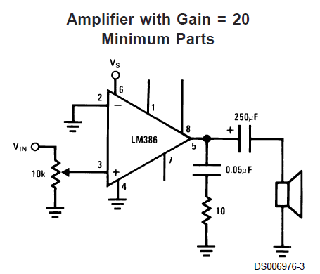
Ignore the amp portion included below and reference the amp schematic I posted earlier.
Also the scope probe is attached to pin 6 of the LM386.
Zeus
Yes.
Also, are you absolutley sure that the LM386 ground is connected?
I'm running out of ideas.
Does the PropScope support AC coupling on the channels? If so, can you grab a screen shot of the LM386 output pin with the PropScope AC coupled and set to the 100mV scale?
>>When I ground the wiper the sound remains, no change.
The '386 amplifies the difference it finds between pins 2 and 3, thus the importance of the same ground point so that extraneous signals are not injected.
- remove C9. This will reduce the gain to 20.
- use the AUD input at R4, not directly at pin3 of the LM.
- R4 must have a lot higher value, something like 330..470kOhm (or reduce R3 so that R4 / R3 ~= 25..100)
- The filter with C8,R5 must be close to the output pin 5.
The output swing from the BS2 can be up to 5Vss. The LM386 has a gain of min. 20, so you need to reduce the signal at the input otherwise the Amplifier is totally overdriven. With the C9 the gain is even higher (200).
Andy
Below is the screen shot you asked for above. Chanel One is Pin 5 and Chanel Two is Pin 6.
Tracy,
I tied the POT ground to Pin 2 as you suggested but unfortunately there was no change. (You meant pin 2, the (-) input, correct?)
Andy,
It is a bit of a mess but I actually used the schematic (LM368) from my original post.
Zeus
I''l try it again but origionally I built the amp circuit on a solderless breadboard and had the exact same result. It is simple enough to reproduce so I will try it again just to see if it repeats.
Zeus
Okay then try it with an additional resistor and capacitor, like that:
Andy
...and the should actually go to ground. I have seen cases where all grounds were connected together, but not connected to the ground on the supply.
Interesting issue. Just red this tread and something came up inside my head; When I look at the picture of the wiring, my first thought was; "That`s a huge antenna". We all know the fact that the BS2 (and other microcontrollers) radiates radio frequency. All the wires helps the radiation go out in the envirement and get stronger than we want, and then make unwanted distortion at other circuits.
I was in a kind of similar issue at a radio repeater station where a BS2 weather station where placed in the same box. When we talked over the repeater, we could hear the BS2 loop in the reciever end. Weather station and radio repeater where galvanic separated from eachother, so the noise came "through the air". Solution of that issue, we moved the weather station (BS2) a bit away from the radio. No noise where present anymore.
So, could it be that your LM386 is recieving the noise via all the wires and then amplifies it? My suggestion is to move the amp a bit away from the bs2 and eventually shield it with alu-plates or something. And make sure that the audio input line is galvanic separated from the bs2 by capacitor.
Sorry for my bad english writing, but I just thought I had to mention my "similar" issue. Hope it helps.
The static/noise seems to be gone and I attribute this to wiring everything up to a common ground as well as separating the amp from the rest of the circuit, however...
Now the only problem that remains is the volume. There does not seem to be any adjustment. Most of the dial (audio taper) produces only faint sound at a higher pitch than expected followed by a brief jump where the sound louder and very distorted, and then the remainder of the adjustment is loud and quite clear. I don't know that the two are related but I am hoping that this sound familiar to someone out there who knows what this is symptomatic of?
Thanks everyone for your input.
Z
If it eventually are logaritmic, you coud maybe get a "jump" in the adio level at a certain point, and the rest of the scale seems to make no difference.
I am using a non-linear POT (Audio Taper) given that it is an audio application, but I will try a linear taper just to see if it repeats.
Z
Update: I just tried a linear 10K POT and while more of the POT is usable there is still no volume adjustment and mild distortion. I think that it is time for me to look into better amplifiers.
Get one and try it. Depending on the input signal strength and impedance, sometimes I have to use the minimum volume setting or severe distortion occurs. You might need to attenuate (weaken) your input signal with an external pot or voltage divider and/or use an audio transformer to match impedances. See also: http://www.radioshack.com/product/index.jsp?productId=2103254
You haven't yet said exactly what is the source of the signal you are amplifying. That would help. If it's a signal that's nearly strong enough to drive a speaker directly, then that's your problem. Even a 20X amp is too much.
Can you provide a scope-shot of the input signal and amplified output?
http://www.ebay.com/itm/New-3-5mm-Portable-Mini-Hamburger-Pocket-Speaker-For-Laptop-PC-iPod-iPhone-MP3-/251357066777
Looks like there was too much gain, much improved when I do not amplify the speaker at all. The funny thing is the other day I thought it might be worth wiring it up directly just to see what would happen, but I did not imagine that it would work without amplification, and I was frustrated with the whole thing, so I never even tried. Lesson learned.
There is still some very minor hum in the speaker but it only bugs me because I know that it is there not because I can actually hear it during normal use. Is the fact that there is still noise in the circuit indicative of a sloppy build or bad code, or should I let it go?
Ironically it could use a little amplification (5 maybe?) but for my use I am happy with the performance.
Thanks everyone for your interest and support.
Chris - It was wired up per the diagram below but Pin 7 was grounded as well. This is the clock that I am building off your crescendo alarm incidentally.
Now on to the enclosure and then my next project.
Thanks again everyone...
Zeus