Shop OBEX P1 Docs P2 Docs Learn Events
help with mini-voltmeter pin out — Parallax Forums

help with mini-voltmeter pin out

davejamesdavejames Posts: 4,047
edited 2014-01-03 16:02 in General Discussion
Hi All,

Some of you have mentioned using these teensy integrated voltmeters:
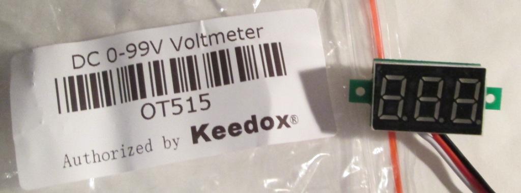
IMG_0079_compressed.jpg
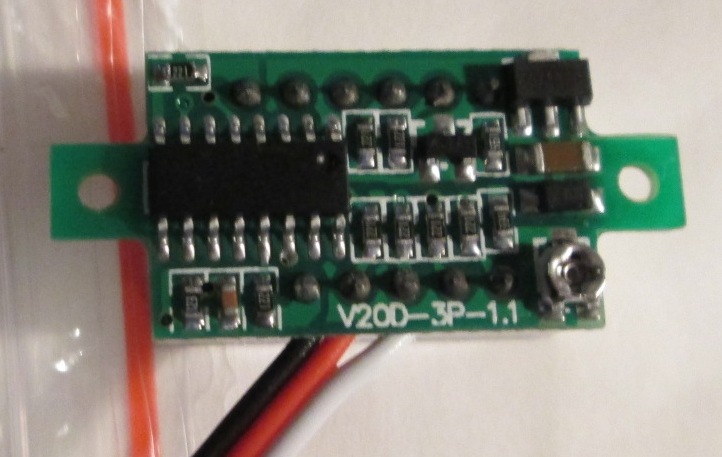
IMG_0080_compressed.jpg


So I bought a few. However, they don't come with any docs. Scrounging the Interweb has resulted in "not much".

If you know about these little beasties, my questions are:

1 - what wire does what? I'm guessing black is ground, red is logic supply and white is for the measured voltage
2 - if red is the logic supply, what's the voltage? 5V? 4.5 to 5.5? Heaven forbid 3V?!?

Thanks.
1024 x 380 - 44K
722 x 457 - 81K

Comments

  • ercoerco Posts: 20,259
    edited 2013-12-30 19:16
    All the ones I have are 2-wire, but I have ordered this 3-wire unit ( en route), which says the supply voltage is 3-30VDC and the measurement range is 0-100V.

    Smoke test time, Pal. Man up! http://www.ebay.com/itm/321224931231?var=510166520774
  • davejamesdavejames Posts: 4,047
    edited 2013-12-30 20:54
    ...man up?!?!

    I'm a wuss, dude. Gotta have the docs.

    But - ok. It's on you if it smokes. :smile:
  • ercoerco Posts: 20,259
    edited 2013-12-30 20:58
    Now why would happy-shop09 lie about the specs?

    Oh, that's right. To sell you another unit after you smoke one!

    IMO 5V sounds like a safe bet. It says reverse polarity protection, so I'd put black to negative, and both red and white to 5V for starters. Once you verify that works, move the white wire to 7 volts and see if the display changes. If not, try the red.
  • xanaduxanadu Posts: 3,347
    edited 2013-12-30 21:14
    Mine says:

    Specifications:
    • Measuring range: DC 0V--32V
    • Input range: DC 2.7V-32V(Max Input: DC 32V. The device can be damaged if input is over 32V)
    • Display: Three 0.36 "digital tube
    • Measurement accuracy: 0.1%
    • Refresh rate: about 300mS / times
    • Input impedance: About 100K
    • Dimensions:33mm*15mm*10mm
    • pitch of holes:28mm
    • aperture size :2.8mm
    • Operation Temp: -10℃-+65℃
    Wiring:
    • red:power supply +
    • black:power supply -, measure -
    • white:measure +
    Package Include:
    • 1x Digital Voltmeter
    But this is what it looks like: (seems different)
    687940223_o.jpg
  • davejamesdavejames Posts: 4,047
    edited 2013-12-30 22:10
    ...ok - found another piece of information on the baggie (non-ESD, natch) that held the unit:

    IMG_0082_compressed.jpg


    Can any Forum member read this scratch?
    634 x 460 - 85K
  • davejamesdavejames Posts: 4,047
    edited 2013-12-30 22:13
    xanadu wrote: »
    But this is what it looks like: (seems different)

    Our two boards are similar.

    Any idea what the little twisty-thingum in the corner is about?
  • davejamesdavejames Posts: 4,047
    edited 2013-12-30 22:14
    erco wrote: »
    IMO 5V sounds like a safe bet. It says reverse polarity protection, so I'd put black to negative, and both red and white to 5V for starters. Once you verify that works, move the white wire to 7 volts and see if the display changes. If not, try the red.

    Sounds like a plan...
  • JLockeJLocke Posts: 354
    edited 2013-12-30 22:54
    davejames wrote: »
    Our two boards are similar.

    Any idea what the little twisty-thingum in the corner is about?

    Looks like maybe a variable capacitor.
  • davejamesdavejames Posts: 4,047
    edited 2013-12-30 23:27
    JLocke wrote: »
    Looks like maybe a variable capacitor.

    Hey J,

    ...mmm...it's a pot. I can see three terminals and an arc of what I presume to be resist.

    Maybe it's a trim to zero in the reading?
  • mindrobotsmindrobots Posts: 6,506
    edited 2013-12-31 03:16
    davejames wrote: »
    ...ok - found another piece of information on the baggie (non-ESD, natch) that held the unit:

    IMG_0082_compressed.jpg


    Can any Forum member read this scratch?

    It says, "Please send your $1 to the erco twins' college fund." I've been seeing this tag in more and more items from ebay China. Hmmm, remember that trip to China erco took a while back?
  • davejamesdavejames Posts: 4,047
    edited 2013-12-31 06:42
    mindrobots wrote: »
    It says, "Please send your $1 to the erco twins' college fund." I've been seeing this tag in more and more items from ebay China. Hmmm, remember that trip to China erco took a while back?

    :smile::lol:
  • trangertranger Posts: 179
    edited 2013-12-31 07:00
    On the baggie, top line is white (白), Second line is red (紅) and Last line is black (黒). I've spent a little time in China and have studied a little Japanese (they use a lot of Chinese characters)

    The red wire is "positive power supply" according to google translate. http://translate.google.com/#zh-CN/en/電源正

    ok, better translation for white (the label is hard to read) "Input positive" google translate: http://translate.google.com/#zh-CN/en/输入正
  • davejamesdavejames Posts: 4,047
    edited 2013-12-31 07:11
    tranger wrote: »
    On the baggie, top line is white (白), Second line is red (紅) and Last line is black (黒). I've spent a little time in China and have studied a little Japanese (they use a lot of Chinese characters)

    ...yes! Thank you.

    That actually makes sense. From the scant docs I've found, the measure range is from 0V to 100V, and that would relate to the white wire.
  • ercoerco Posts: 20,259
    edited 2013-12-31 07:13
    davejames wrote: »
    ...ok - found another piece of information on the baggie (non-ESD, natch) that held the unit:

    IMG_0082_compressed.jpg


    Can any Forum member read this scratch?

    Funny you should ask, Dave! http://forums.parallax.com/showthread.php/150882-15-Rotary-Quadrature-Encoder-400-PPR?p=1218492&viewfull=1#post1218492

    Just look at the first character of the attached chart:

    Top White 0-100V
    Middle Red 0-30V
    Bottom black common ground
    385 x 370 - 56K
  • davejamesdavejames Posts: 4,047
    edited 2013-12-31 07:17
  • davejamesdavejames Posts: 4,047
    edited 2013-12-31 08:50
    ...okey dokey - it works!

    IMG_0083_compressed.jpg


    Black to ground.
    Red to +5V.
    White to a 120VAC->12VDC adapter output.

    And the "teeny twistum thing" on the back of the unit is a reading zeroing trim pot - verified.

    Thanks everybody.
    1024 x 621 - 94K
  • xanaduxanadu Posts: 3,347
    edited 2013-12-31 11:24
    So it looks like we have an official mini-voltmeter club going here.

    I propose we establish a binder with our Code of Conduct and Standard Operating Procedures. We should probably get hats or badges with pictures to make it official.
  • ercoerco Posts: 20,259
    edited 2013-12-31 11:39
    Nice Fluke multimeter, DJ! I suppose you can afford such a pricey gadget with all the dollars you've saved from erco's daily deals.

    May I remind you about the freebie this poor (prior to today's African inheritance, anyway) father of twins has been forced to use all along?

    My free Parallax "Inventor's Wand" is also clearly visible on the desk. :)
  • davejamesdavejames Posts: 4,047
    edited 2013-12-31 12:04
    erco wrote: »
    Nice Fluke multimeter, DJ! I suppose you can afford such a pricey gadget with all the dollars you've saved from erco's daily deals.

    Thanks. Actually, that's just one of 5 Fluke meters that I have in my vast array of tech gear...:smile:

    Oh, and I didn't get these units via EDD - bought 'em off Amazon.
  • davejamesdavejames Posts: 4,047
    edited 2013-12-31 12:08
    xanadu wrote: »
    So it looks like we have an official mini-voltmeter club going here.

    Well, you know - these things are great! I had previously bought parts to build essentially the same thing, but these wind up being cheaper in the long run.
  • ercoerco Posts: 20,259
    edited 2013-12-31 12:09
    @DJ, AKA Mr. Moneybags: I just noticed that you sprung for the pricier BLUE LED voltmeters. I guess if you've got it, flaunt it! :)
  • skylightskylight Posts: 1,915
    edited 2013-12-31 18:07
    How about this one it displays V A and Frequency.

    Comes with CT included.
  • davejamesdavejames Posts: 4,047
    edited 2014-01-01 01:10
    skylight wrote: »
    How about this one ....

    That was one scary Ebay page! :surprise:
  • RDL2004RDL2004 Posts: 2,554
    edited 2014-01-01 08:51
    How about this one it displays V A and Frequency.

    The shipping is 10 times the selling price!
    Do people still fall for that?
  • skylightskylight Posts: 1,915
    edited 2014-01-01 11:30
    I always check the shipping but I thought that was a reasonable price all in for the extra functionality
  • LevLev Posts: 182
    edited 2014-01-01 14:05
    davejames wrote: »
    Hi All,

    Some of you have mentioned using these teensy integrated voltmeters:
    IMG_0079_compressed.jpg
    IMG_0080_compressed.jpg


    So I bought a few. However, they don't come with any docs. Scrounging the Interweb has resulted in "not much".

    If you know about these little beasties, my questions are:

    1 - what wire does what? I'm guessing black is ground, red is logic supply and white is for the measured voltage
    2 - if red is the logic supply, what's the voltage? 5V? 4.5 to 5.5? Heaven forbid 3V?!?

    Thanks.
    This might be helpful:

    https://www.adafruit.com/products/705#Description
  • davejamesdavejames Posts: 4,047
    edited 2014-01-01 20:13
    Lev wrote: »

    Thanks Lev.
  • davejamesdavejames Posts: 4,047
    edited 2014-01-03 16:02
    ...and, it's been hacked (literally) into my pedal board power supply prototype.

    The hack (aka "thank God for RTV!"):
    IMG_0088_compressed.jpg


    Select switch center off (1k pull down mounted on the switch maintains a zero input):
    IMG_0085_cropressed.jpg


    One of the two variable (4.5V to 9.0V) outputs selected:
    IMG_0086_cropressed.jpg


    Thanks again for the tip on these nifty little tools!
    1024 x 768 - 115K
    1024 x 736 - 82K
    1024 x 721 - 74K
Sign In or Register to comment.