

RUNNING LINEAR ACTUATOR without feed back
 ajit.nayak87
Posts: 76
ajit.nayak87
Posts: 76
Dear all.
Here i am trying to do simple algorithm.I wanna formula to calculate actual position in algorithm
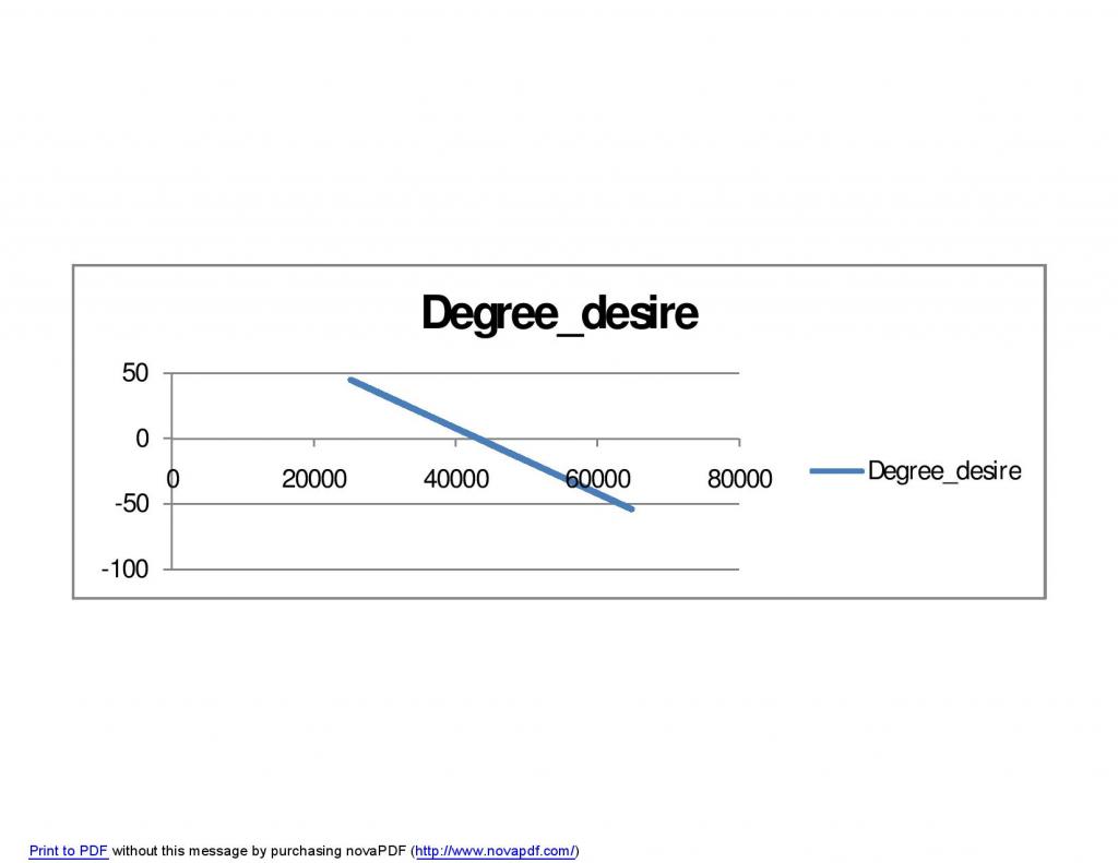
Desired angle calculation:
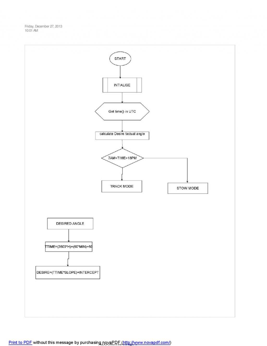
desired angle=-0.00227272727273x + 102.272727273 where x= (3600*hour)+(minute*60)
actual angle:actual actuator stroke is 600mm ,3.2mm/sec speed ,0.192mm/min. I wanted to run actuator from morning 7 AM to 18PM. approximately 11 hour/660 minutes,How can i convert this mm/min movement into 45 deg to -45 deg .
7AM assume deg :45 , 0mm actuator initial length
12:30 assume deg :0 , 300mm length
18:00 assume deg -45,600mm actuator final length.
Here i am trying to do simple algorithm.I wanna formula to calculate actual position in algorithm
Desired angle calculation:
desired angle=-0.00227272727273x + 102.272727273 where x= (3600*hour)+(minute*60)
actual angle:actual actuator stroke is 600mm ,3.2mm/sec speed ,0.192mm/min. I wanted to run actuator from morning 7 AM to 18PM. approximately 11 hour/660 minutes,How can i convert this mm/min movement into 45 deg to -45 deg .
7AM assume deg :45 , 0mm actuator initial length
12:30 assume deg :0 , 300mm length
18:00 assume deg -45,600mm actuator final length.
1024 x 1325 - 53K

1024 x 791 - 36K
Comments
In order to compute the angle you'd probably want to use trig. The angle will be dependent on the geometry of the actuator. It's unlikely the angle will have a linear relationship to the actuator's length.
I see you gave additional information in another forum.
But I don't think you gave any information about the geometry of the actuator. How is the actuator connected to the component with the changing angle?
Yes i am trying to calculate angle depend on distance traveled by actuator.How can i do that to match with Desired angle.SO i need actual angle to movement able so that if i say desire angle as 0 deg .Actual angle(length as to be moved so much mm). actuator speed is 3.2mm/sec.0.192mm/min.Now how i could convert it to Actual angle
Desired angle/ Desired mm i am assuming to be desired angle=-0.00227272727273x + 102.272727273 where x= (3600*hour)+(minute*60)
Now i need to calculate Actual angle
we know speed =(dist/time)=time taken full retract =(600/3.2)=187.5sec
how can calculate actual angle????
As I said before, this will depend on the geometry of your setup.
If the relationship between actuator and angle is linear then it's simple equation of a line. Y is the angle and X is the position.
X1, Y1 = (0, -45)
X2, Y2 = (600, 45)
Your slope is 90/600 = 3/20
Your y-intercept is -45.
so:
angle = ((3 * position) / 20) - 45
or
position = ((angle + 45 . . . redacted
Why do I get the feeling this is a homework assignment?
Maybe you can tell us more about your project if you need more help. I'm not comfortable doing all the calculations.
What I posted should get you most of the way there.
The other thing you should remember is distance = rate * time.
With this and a little algebra you should be able to compute any one variable based on the others.
Again, this assumes your actuator changes the angle in a linear fashion, which is rarely the case when using a linear actuator to rotate something.
I am assuming approximate sun elevation angle.
Assumed : tracking start from morning 8Am (say) with elevation 45 deg actuator fully retracted(600mm).12:30 pm assume elevation angle is almost 0 parallel to surface actuator position is @ middle(300mm length). and around 18pm elevation will be -45 deg .actuator length:0mm
after 18pm desired angle assumed:0 degree and actuator pos:300mm length.
If you just want the actuator to move the same amount throughout the day, then it's kind of easy.
11hr*60minute/hour = 660minutes
so turn on the actuator once a minute for (25 / 88) seconds per minute.
Here's the math:
600mm/660minute = 10/11 mm each minute
since your actuator move 3.2mm/second
time * 3.2mm/sec = 10mm / 11
time = (10 / (11 * 3.2)) (get rid of decimal by multiplying top and bottom by ten) = (100 / 352) (divide top and bottom by four to reduce fraction) = (25 / 88) seconds per minute
This is less than a third of a second per minute. You might be better off selecting a time to run the actuator and calculate the how often to run the actuator.
Let's say you want to run it for two seconds at a time.
Then:
2 * (88 / 25) = (176 / 25) minutes
So you'd run the actuator for two seconds every 7.04 minutes (7 minutes, 2.4 seconds).
Just change the "2" above to figure out how frequently you should run the actuator if you want it on for a different number of seconds.
Here's the other equations relating the various variables to each other.
angle= ((3 * position) / 20) - 45
or
position =((angle + 45) * 20) / 3
position = ((20 * angle) / 3)+ 300
since position = 3.2 * time (in seconds)
angle =((3 * 3.2 * time) / 20) - 45
using only integers:
angle =((96 * time) / 200) - 45
Again, this isn't going to be precise without knowing the geometry of your setup.
2 * (88 / 25) = (176 / 25) minutes
So you'd run the actuator for two seconds every 7.04 minutes (7 minutes, 2.4 seconds).
i am trying to understand Where these value has put in below equation??
Just change the "2" above to figure out how frequently you should run the actuator if you want it on for a different number of seconds.
Here's the other equations relating the various variables to each other.
angle= ((3 * position) / 20) - 45
or
position =((angle + 45) * 20) / 3
position = ((20 * angle) / 3)+ 300
position = 3.2 * time
how can made time as variable???
2 * (88 / 25) = (176 / 25) minutes
The above is if you wanted to run the actuator for two seconds at a time. The general equation would be:
(time between turning on actuator in minutes) = (seconds actuator will be on) * (88/25)
I don't use the Arduino much so I don't know how you'd keep track of time using the Arduino.
Arduino is simple as Writing normal C .
code
double Desire_Degree;
unsigned int TS;
static float slope= 0.00227272727273;
static float intercept=- 102.272727273;
static int length;
double Actual_Degree;
static int h;
static int m;
static float ACT_SPEED=3.2;
void setup()
{
h=7;
m=30;
Serial.begin(9600);
}
static int time_interval;
void loop()
{
calc_min();
//Desire degree calculation
if(h<23)
{
TS=(3600*h)+(60*m);
Desire_Degree=(TS*slope)+intercept;
//Actual anngle calculation
time_interval=(10)/(11*ACT_SPEED);
length=3.2*(60)*(88/25);
Actual_Degree=((96*time_interval)/200)-45;
// actual_deg=((3*length)/200)-45;
Serial.print("HH-MM: ");
Serial.print(h);Serial.print(":");Serial.println(m);
Serial.print("Desired Degree:");
Serial.println(Desire_Degree);
Serial.print("Actual Degree:");
Serial.println(Actual_Degree);
Serial.print("length:");
Serial.println(length);
Serial.println(".................................");
}
delay(1000);
}
void calc_min()
{
if(m<60)
{
m=m+5;
}else if(m==60)
{
m=0;h=h+1;
}
}
I thought that's what I've been doing?
Maybe someone else can help you more. I don't know how to keep time on the Arduino.
In above code i am just incrementing the time fro every 5 min. And calculating Desired angle and actual angle.
In setup()-. intialise serial port and time to 7:00
loop is like main program in C which keep executing.
Above code:
how position or angle calculated on time basis.from below equation angle directly proportional to position of actuator.
angle= ((3 * position) / 20) - 45
or
position =((angle + 45) * 20) / 3
position = 0
angle = -45
then in your main loop you need some way of waiting 7 minutes 2.4 seconds (if using a 2 second on time)
once the program as waited 7 minutes 2.4 sec then turn on the actuator for 2 seconds.
You can then update your position and angle variables using just the slope from these equations.
"angle = ((96* time) / 200) - 45"
since time was 2 you'd use:
angle += (96 * time) / 200
or
angle += 0.96
Maybe instead of a two second on time you want the angle to change 1 degree each time the actuator is on.
In which case you'd divide the total time by 90 and the total distance by 90 so every 660/90 minutes you'd turn on the actuator (600/90)/3.2 second = 2.0833 seconds.
660/90 = 22/3 minutes = 7 minutes 20 seconds
In this case you's loop your program every 7min 20s.
Again you'd start with:
position = 0
angle = -45
Now every loop you'd:
power actuator for 2.083 seconds
position += (20/3)
angle++
But again, this isn't really going to be correct unless the angle and position have a linear relationship. This is unlikely when using a linear actuator to rotate some thing.
IMO, best you can do is experimentally make a lookup table and program that in, based on the assumption that the panel will move in small blips at a time.
Of course, a simple optical tracker that looked at the position of the sun instead of a lookup table would be easier and more accurate, plus it would obviate the need for the timing algorithm specified in your school assignment. Numerous examples extant.
As i told i am converting time to Total Second . It give me the constant angle
I already feel silly with how much detail I've gone into in this thread.
Apparently I don't understand what you are asking. I'll leave this to anyone else who cares to resume the discussion.
This brings to mind the old saying: You can lead a horse to water but ....
The swept angle vs OnTime, will be non linear for a Linear actuator driving an arm.
You can also expect the moved distance to vary with Temperature, wind loading, weather, and Power supply.
All of that makes open-loop, more of a lottery than a control design solution.
It is relatively simple to design a optical tracking system, with sensors that seek peak illumination (which may not even be the location of the sun). That is the smarter solution.
You could, however, design a combination, - use some simple position checker, like an Optointerruptor, and combine with impulse drive.
The drive can 'learn', and remember the Time/Angle for that traverse.
That way, a single sensor fault does not make the system fail, and you do not need to get the alignment origins precise.
Can we use Linear actuator with Feedback like hallsensor, linear encoder,variable potentiometer Where we can track linear actuator movement.
Either a resistance potentiometer or pulses from a hall sensor or reed switch.
Duane J
All scaling has the following can be done using three equations. (before anyone comes along and says 'Jordan, I've only ever used one or two', bear in mind that many applications can cancel out terms.)
Lets take the given values from the top post, converting a mm position to an angular one, and using the same assumptions given. We can set some initial values:
Input Min (Imin) = 0
Input Max (Imax) = 600
Scaled Min (Smin) = -45
Scaled Max (Smax) = 45
First, we can calculate Slope (m):
m = (Smax - Smin) / (Imax-Imin) = (600-0) / (45-(-45)) = 0.150
From there we calculate our Offset (b):
b = Smin - ( Imin * m) = -45 - (0 * .150) = -45
Now, can calculate any desired position where x = Input_Value and y = Scaled_Output. For instance, at 30mm:
y = mx +b = (0.150)(30) - 45 = 40.5
This method works for all linear scaling. If you want a time_in_minutes converted to a desired angle, then your Imin and Imax would be 0 and 660, respectively.
Hope this helps point you in the right direction.
Something like this?
Linear to Rotary motion.
Steve Garrison's Vertical Axis Tracking Mount based on a Satellite Dish Mount.
Duane J
That was a fast lookup, I'm impressed!
Hal
Yes, the cable, strap, etc. or rack and pinion gear would be a linear relationship between position and angle. It is when the mechanical linkage is similar to the steering linkage on a lawn tractor that it becomes non-linear.