Design Critique Wanted
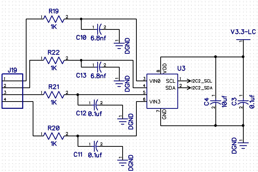
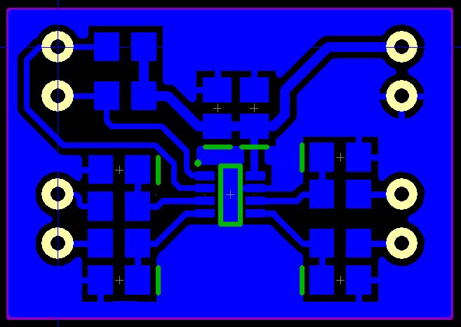
I'm working on a ADC module that I can easily add to various projects. I'm using the AD7995 from Analog Devices. It's a little 4chan, 10bit, ADC in an SOC sized package. Since the interface method is I2C I wanted to build in some low-pass filtering to help cut down on the noise I sometimes see in the readings. To that end I added an R/C low-pass to the circuit but analog electronics has always been my weakness. I have two different filters on the board. One is designed with a cutoff of around 24KHz figuring that would possibly allow for audio sampling but reject the 50Khz noise I see from the little switcher modules I often use. The other has a cutoff of about 1.5Khz for sampling battery voltages and other slow moving stuff.
What I'm not sure of is the interaction with the resistor in the filter. My meter suggests that the additional resistor does not change the voltage and as it's really another ADC at heart I figured that was a decent test. I know op-amps are often recommended to feed the ADC but I need the module to remain very small so no room to add that in. Does this seem like a reasonable design? I'm planing to incorporate this into my robot as well but wanted a few more eyes on it before I commit it to copper. Any feedback or reprimands are welcome.
Thanks for looking.


