

My first designed PCBs arrived in the mail.

I have been learning how to make PCBs with diptrace and had sent off my first creation to OSH Park for manufacture.
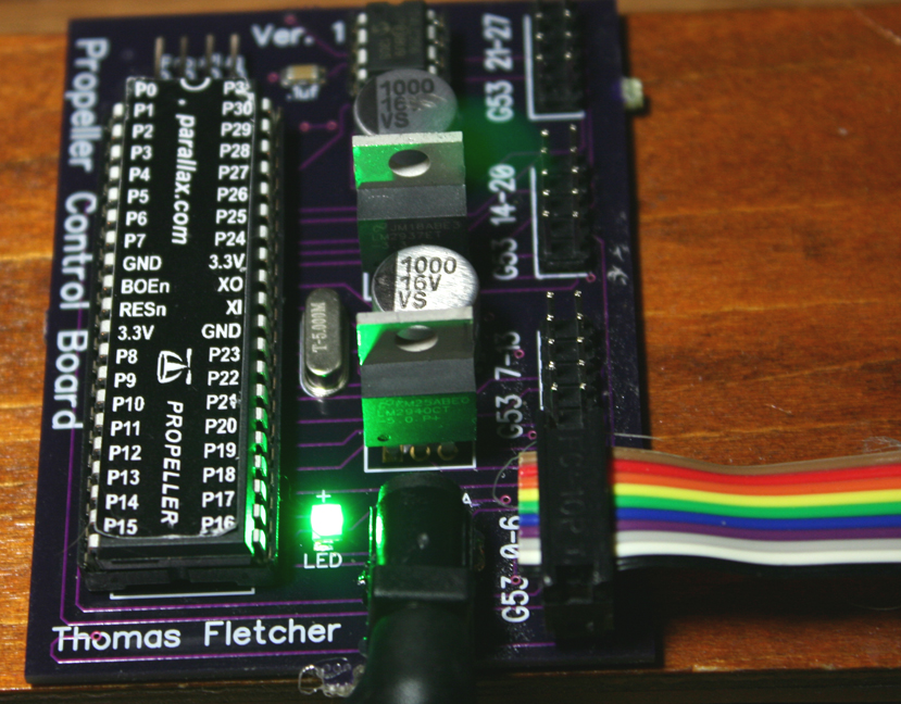
They came back and so far so good. I haven't tested all the pins yet but Pin 0 is going out the first header and
I am able to program both the propeller and EEPROM. so yea!
I thought of a good name for the board AFTER sending the order in. Should of called it the Quick In&Out as that is
my "design philosophy" for it.
I wanted a controller that I could quickly change out between projects and I used DIP chips because I wanted
to be able to easily change them out also.
829 x 648 - 474K
Comments
I've wanted to learn PCB design for at least ten years now, but my day job (same as the night job) prohibit me from really getting started. Then there's the fact that Parallax has around six people who can already do this job, so with a bit of prodding I might be able to talk one of them into a project. I'm inspired by your work and hopefully I'll make the time over the holidays to learn to do this as well.
I'm still struggling to learn Eagle so I can create a small PCB. Progress is slow!
Amanda
I like the way diptrace has them under tabs separated by type of component and even tabs
for manufactures like Parallax.
Doc
Glad I did as the 10 pin female headers were wider then the male headers. Something
I caught by doing this.
Good advice about testing component layout with thin paper and a foam substrate. I use that green fake flower base foam. After looking at so many datasheets and making components and patterns for the parts that are not in the library, it is easy to misjudge the size of a part.
May I ask what connectors and ribbon cable you used? Those look nice!
Cable
https://www.sparkfun.com/products/10649
Connector
https://www.sparkfun.com/products/10650
Just noticed they have 2x5 Pin Shrouded Header (male) also but I just use
two row break away headers I got off ebay.
Each 10 wire set has a ground, 5V, 3.3v as the left three wires and then 7 of the propeller
pins as the next wires left to right.
prop board 10 headers only.zip
Enjoyed watching the video. I've only got very little experience soldering SMT components and I generally find it so challenging that I take it to our production staff. Of course they've got magnification, hot air pencils, etc.
I really want to learn how to do a PCB layout and will install DipTrace before the holidays. This year we're staying home so I should have some time to learn a new skill.
Keep going with the projects. I'll enjoy watching the progression.
Ken Gracey
I haven't climbed that hill yet. I've started a few board in Express PCB and Eagle CAD, but I always find a missing components in the library that stops me dead in my tracks. Defining a component seems like so much work that going back to point to point wiring on strip board seems easier. But that's because I tend to just do one offs so their's no ROI that you would get with multiple PCB's.
Parallax's Quickstart which does more on board, but I like to start bare bones and wanted a board for
semi-permanent projects. Those 2x5 connectors hold really well. Have to rock them off.
I also wanted something case ready. All those shields are nice but I don't know how they manage
to use them in a cased project. The ribbon cable gives me the ability to reach anywhere I need the components.
So I was willing to pay the price for the functionally I was looking for, plus it was nice
not having the rat nest of wires to connect those 40 pins. I wired a few similar boards by
hand and it was a real hair puller.
When I was in school, I used Altium Designer software for layout and schematic. I'm out of school now and I don't want to spend money on pricey software. I just learned Diptrace a couple weeks ago, I find it MUCH better/easier than Eagle. A big plus is that there is a Parallax library
Anyway, I did my first board too with Diptrace and OSH Park (I received it this week!!), here are some pictures :
This board is used to control a cheap disco ball bought on Ebay. I'm connecting it with a Raspberry PI that host a webpage to control the hardware of the disco ball. Also, I created a scripting language to make light/motor sequences and it is compiled and put in the last section of the propeller EEPROM.
Fred
xbox controller remote control project.
It's not hard but it can take a bit of practice. If you can find a broken/old PCB with a TQFP chip on it, you could try unsoldering it, clean the chip and then soldering it again. You don't need a fine tip soldering iron but I suggest you buy some liquid rosin flux (http://www.electronicplus.com/images/products/10-4216.jpg) and unsoldering braid.
you start by putting a bit of solder on let's say the top-left pad and bottom-right pad. After that you align the IC with all the pad and you secure it in place by soldering the 2 pads in diagonal. Then you can pour a bit of flux all around the chip and start soldering. When you solder that kind of package, try to avoid putting your iron directly on the pins, you only have to touch the pads with your iron, else you will end up with a lot of solder bridge and you will have to remove them with the braid and start over for the bridged pins. If you can find really thin soldering wire, it really helps because you only need a tiny amount of solder on each pad (once again to avoid solder bridges between pins).
After everything is soldered, your PCB will be messy because of the flux, you need to clean it with isopropyl alcohol (rubbing alcohol).
Hope it helps, and don't hesitate to ask any question!
I have switched to nearly all SMD parts now. My home prototypes are faster with less drilling and it's not hard to solder the SMT resistors and caps with hot-air. I've even done a couple of the SMT prop chips now and it's a bit more challenging but not to bad. 805 components are reasonably easy to work with and someday I venture on to 603 sized stuff. It sure makes life easier to fit things minus all the space for caps and resistors. SOIC chips are a breeze to do. Smaller packages and pin spacing gets more challenging. Just like Fred said though, once you tack down the corners its very quick to hit the rest of the pins. Use the braid to clean up small bridges and your good.
I like hot air for the SMD diodes, resistors, and caps. A tiny dab of paste on each pad. Place the parts with tweezers and then hit it with the heat till it just melts and they pretty much self-align. Just got to be careful not to get the nozzle too close or they take to flight. I'm starting to switch to hot-air for the chips too. I get fewer bridges that way. I use stripped solid core wire to dab a small bit of paste on each pad and a thick flux to glue the chip down. Then hit one side with hot air, cool, and hit the other side.
SOT packages are the ones I have the most trouble with.
I got my solder / hot-air station from EBay. It was worth every penny.
I do all my soldering with the iron, but I might be tempted to try hot air gun. Some of the chips I want to solder have a ground pad on the bottom so I suppose it's better with solder paste. I have this hot air gun that I use for heat shrink tube : http://canada.newark.com/ultraheat/34100/sv800-heat-gun-120v-950-f/dp/86R9716
It can go to 950F (510°C) So I suppose it could melt solder... Where do you buy your solder paste?
Unless you enjoy frustration don't try to do this with a heat-gun like that. You want something that just barely puffs out air and even then it's still easy to overdo it and push things around.
I picked up this and so far it's been good but if you already have a nice soldering iron then you can find just the hot-air station for less.
http://www.ebay.com/itm/4-IN-1-X-TRONIC-9020-XTS-HOT-AIR-REWORK-SOLDERING-IRON-STATION-FUME-EXTRACTOR-/110969755108?pt=LH_DefaultDomain_0&hash=item19d65015e4
Even on the lowest air setting though with a small nozzle its easy to blow a part off if you get too aggressive.
I ordered my paste from Zephertronics (sp?). Can't say I would recommend them as it took weeks to finally get them to ship my order but it's clear that it will last me years of prototyping before I use up the two syringes I purchased. They also sell a really thick flux, almost like honey, that is great for tacking parts down. That of course will not hold them once the heat is applied but it makes it easy to work with the board while you place them all. After that the surface tension of the solder really takes care of the alignment on the tiny parts. If you are worried about the ICs you can still hand solder those but honestly once I started using air on them I found it easier and the results look nicer.