

Project Multi-Sensor Quadcopter
 jackemoore
Posts: 4
jackemoore
Posts: 4
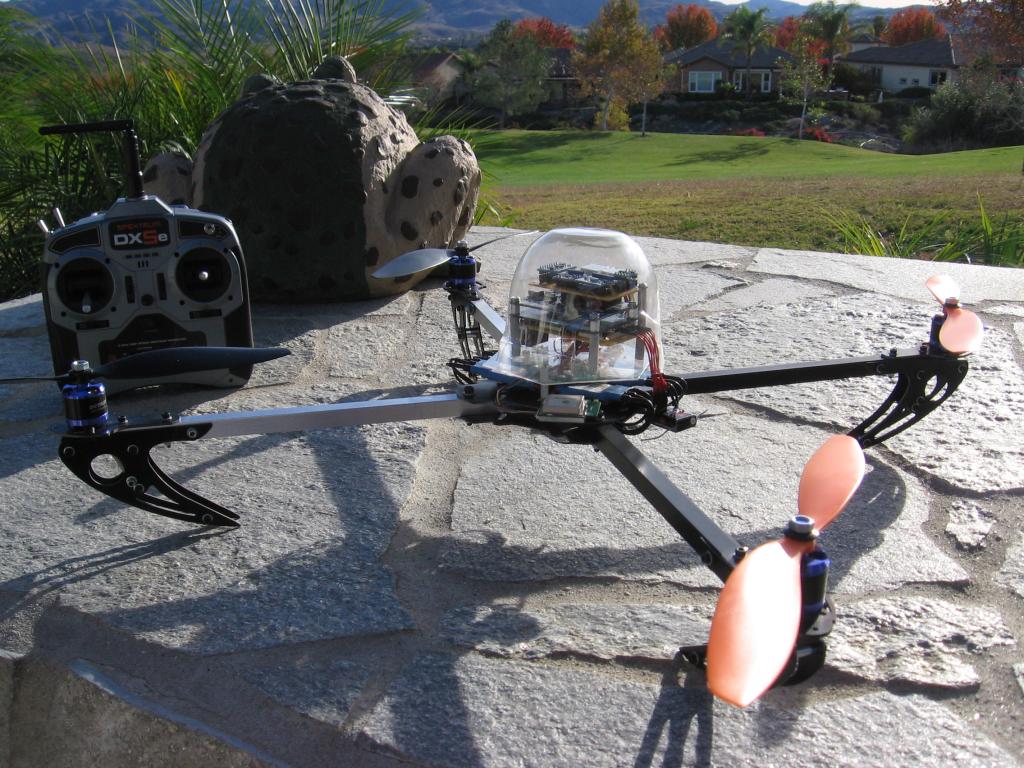
This project I've been working on the last two months is my first prop's project. Prior experience is with Lego Mindstorms and Basic Stamp 2 projects. I purchased a Dynam Quadcopter 650 with the idea of creating my own flight controller using Parallax sensors. I wanted a low cost basic frame that I could expand upon and my quad objectives are a camera payload and self leveling, self hovering, and waypoint navigation, in addition to R/C ground control backup.
I've nearly completed basic testing and in process of adding ultrasonic distance sensors to improve performance near ground level (i.e., quad aerodynamics from wind velocity and ground effect when the ground interrupts the airflow under the quad). I do not have presentable schematics, but plan to fully document the entire project when the quad design nears completion and performance is looking to achieve all my objectives.
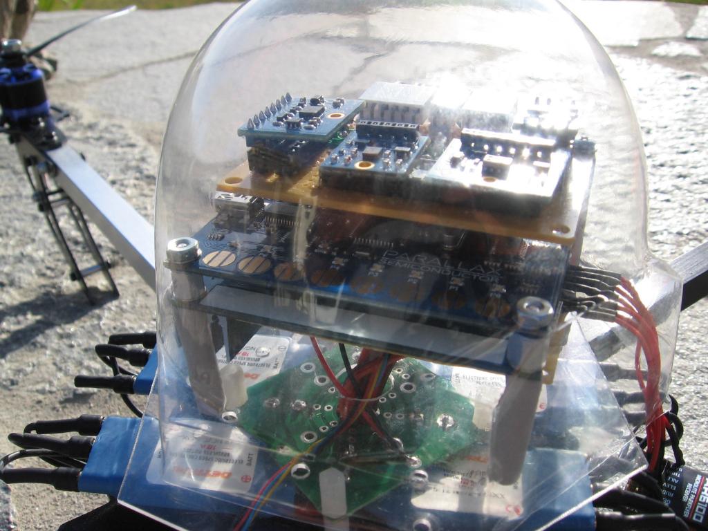
The core of this quad flight controller is multiple Propeller Quickstart boards talking to one another. One Quickstart (Quad Sensors) is interfacing with the tilt and positioning sensors, another Quickstart (Quad Rotors) is handling the Pulse Width Modulation (PWM) devices (motor speed controllers and R/C receiver) and Ultrasonic Distance sensors located at each motor pod, while a third Quickstart is in the planning stage to support an on-board camera and video recording (SD Card & Wireless). Currently, all the processors (16 cogs) are being utilized in the Quad Sensors and Quad Rotors boards. [Original 12/01/2013] This design maintains a 5 ms inner loop to provide corrections to the motors using tilt velocity sensor updates, tilt position updates are applied every 100 ms and height & location updates are applied at a 1Hz rate. Actual tilt position updates are at a 160 Hz rate, but currently, these are being applied at a 10 Hz rate inside the inner control loop. [Revised 12/07/2013] Changed design where inner loop is 10 ms inclusive of both tilt velocity and tilt position updates. 1 Hz loop remains for GPS location and altimeter zenith position updates. Have completed integration of ultrasonic distance sensors located at each motor pod, software driver (PASM) completed and now ready to begin integration of US sensors, altimeter and GPS height data to advance altitude hold function.
Coding for the interface drivers started with coding examples accompanying each of the Parallax modules and what I could find in Propeller Object Exchange (OBEX). In general, functionality remained in the resultant coding, but were heavily modified particularly when SPIN drivers needed to run faster and were converted to assembly language. The coding for the inner flight control loop started with Jason Dorie's QuadX Gyro Only source code. Again, because of my design differences, this was modified to meet my specific needs.
Tuning of the Proportional, Integral, and Derivatives functions of a PID controller has its complexities and is always a challenge. I haven't attempted something akin to Jason's on-the-fly tuning using a ground station controller or instrumented quad dynamics in an offline analyzer, but have simply used some rules-of-thumb and trial & error in controlled configurations. I've achieved reasonable stability with backup corrections using an R/C transmitter. [Original 12/01/2013] Adding ultrasonic distance above ground sensors is my next step towards hopefully achieving a reliable self stability. [Revised 12/08/2013] Auto leveling appears to be working using combined gyro, accelerometer and compass providing roll, pitch and yaw stability. Completed hardware integration of ultrasonic sensors located at each motor pod, PASM driver and ready to begin testing of altitude hold function.
Features:

Tri-P8X32A Propeller Quickstart Boards (ID 40000)
Each Board is attached via header connector to a PC Board w/holes for mounting modules & components
Gyroscope Module 3-Axis L3G4200D (ID 27911)
MMA7455 3-Axis Accelerometer Module (ID 28526)
Compass Module 3-Axis HMC5883L (ID 29133)
Altimeter Module MS5607 (ID 29124)
PMB-688SiRF GPS with Internal Antenna (ID 28501)
Four 700KV Motors with 11 x 4.7 Propellers (Dynam)
Four 18A ESC (Dynam)
AR6100 or AR6200 DSM2 6-Channel Receiver (Spektrum)
Four Ultrasonic Distance Sensors (ID 28015)
SD Card Adapter Kit (ID 32313)
Quad Sensors Quickstart Board:
3-Axis Gyro Angular Velocity Sensor (3-wire SPI PASM driver)
Calculated tilt angles using discrete integral (Adams-Bashforth 2nd Order integration)
3-Axis Accelerometer Angular Position Sensor (3-wire SPI PASM driver)
Calculated tilt angles using scaled integer sin, cos, atan2 trigonometry functions
Combined Gyro tilt angles & Accelerometer tilt angles using Angle Complementary Filter
3-Axis Compass Horizontal Angular Position Sensor (I2C & DRDY PASM driver)
Compensated for tilt angles and local magnetic disturbances (calibration offsets & scale)
Magnetic heading translated to true heading using magnetic declination
Altimeter Vertical Position Sensor (I2C & CS SPIN driver)
Corrected altitude and sea-level pressure using GPS altitude reference
3-Axis GPS Position, SMG, COG, UTC Time Sensor (1-wire serial SPIN driver)
1 Hz capture and decode of GGA & VTG NMEA messages
DGPS (differential GPS) using WAAS (wide area augmentation system) receiver corrections
Propeller-to-Propeller Half-Duplex Serial Communication (I2C with RTS & CTS SPIN driver)
Quad Rotors Quickstart Board:
Four Electronic Speed Controllers (ESC's) that drive Four Brushless Motors (PWM PASM driver)
6-Channel R/C Receiver (PWM PASM driver)
Four Ultrasonic Vertical Distance Above Ground Sensors (1-wire TTL PASM driver)
Propeller-to-Propeller Half-Duplex Serial Communication (I2C with RTS & CTS SPIN driver)
Quad Camera & Video Recording Quickstart Board:
Camera (type and driver to be determined)
SD Card Adapter (driver to be determined)
Wireless Ground Station Communication (type and driver to be determined)
Propeller-to-Propeller Half-Duplex Serial Communication (I2C & CS with RTS & CTS SPIN driver)
[
I've nearly completed basic testing and in process of adding ultrasonic distance sensors to improve performance near ground level (i.e., quad aerodynamics from wind velocity and ground effect when the ground interrupts the airflow under the quad). I do not have presentable schematics, but plan to fully document the entire project when the quad design nears completion and performance is looking to achieve all my objectives.
The core of this quad flight controller is multiple Propeller Quickstart boards talking to one another. One Quickstart (Quad Sensors) is interfacing with the tilt and positioning sensors, another Quickstart (Quad Rotors) is handling the Pulse Width Modulation (PWM) devices (motor speed controllers and R/C receiver) and Ultrasonic Distance sensors located at each motor pod, while a third Quickstart is in the planning stage to support an on-board camera and video recording (SD Card & Wireless). Currently, all the processors (16 cogs) are being utilized in the Quad Sensors and Quad Rotors boards. [Original 12/01/2013] This design maintains a 5 ms inner loop to provide corrections to the motors using tilt velocity sensor updates, tilt position updates are applied every 100 ms and height & location updates are applied at a 1Hz rate. Actual tilt position updates are at a 160 Hz rate, but currently, these are being applied at a 10 Hz rate inside the inner control loop. [Revised 12/07/2013] Changed design where inner loop is 10 ms inclusive of both tilt velocity and tilt position updates. 1 Hz loop remains for GPS location and altimeter zenith position updates. Have completed integration of ultrasonic distance sensors located at each motor pod, software driver (PASM) completed and now ready to begin integration of US sensors, altimeter and GPS height data to advance altitude hold function.
Coding for the interface drivers started with coding examples accompanying each of the Parallax modules and what I could find in Propeller Object Exchange (OBEX). In general, functionality remained in the resultant coding, but were heavily modified particularly when SPIN drivers needed to run faster and were converted to assembly language. The coding for the inner flight control loop started with Jason Dorie's QuadX Gyro Only source code. Again, because of my design differences, this was modified to meet my specific needs.
Tuning of the Proportional, Integral, and Derivatives functions of a PID controller has its complexities and is always a challenge. I haven't attempted something akin to Jason's on-the-fly tuning using a ground station controller or instrumented quad dynamics in an offline analyzer, but have simply used some rules-of-thumb and trial & error in controlled configurations. I've achieved reasonable stability with backup corrections using an R/C transmitter. [Original 12/01/2013] Adding ultrasonic distance above ground sensors is my next step towards hopefully achieving a reliable self stability. [Revised 12/08/2013] Auto leveling appears to be working using combined gyro, accelerometer and compass providing roll, pitch and yaw stability. Completed hardware integration of ultrasonic sensors located at each motor pod, PASM driver and ready to begin testing of altitude hold function.
Features:
Tri-P8X32A Propeller Quickstart Boards (ID 40000)
Each Board is attached via header connector to a PC Board w/holes for mounting modules & components
Gyroscope Module 3-Axis L3G4200D (ID 27911)
MMA7455 3-Axis Accelerometer Module (ID 28526)
Compass Module 3-Axis HMC5883L (ID 29133)
Altimeter Module MS5607 (ID 29124)
PMB-688SiRF GPS with Internal Antenna (ID 28501)
Four 700KV Motors with 11 x 4.7 Propellers (Dynam)
Four 18A ESC (Dynam)
AR6100 or AR6200 DSM2 6-Channel Receiver (Spektrum)
Four Ultrasonic Distance Sensors (ID 28015)
SD Card Adapter Kit (ID 32313)
Quad Sensors Quickstart Board:
3-Axis Gyro Angular Velocity Sensor (3-wire SPI PASM driver)
Calculated tilt angles using discrete integral (Adams-Bashforth 2nd Order integration)
3-Axis Accelerometer Angular Position Sensor (3-wire SPI PASM driver)
Calculated tilt angles using scaled integer sin, cos, atan2 trigonometry functions
Combined Gyro tilt angles & Accelerometer tilt angles using Angle Complementary Filter
3-Axis Compass Horizontal Angular Position Sensor (I2C & DRDY PASM driver)
Compensated for tilt angles and local magnetic disturbances (calibration offsets & scale)
Magnetic heading translated to true heading using magnetic declination
Altimeter Vertical Position Sensor (I2C & CS SPIN driver)
Corrected altitude and sea-level pressure using GPS altitude reference
3-Axis GPS Position, SMG, COG, UTC Time Sensor (1-wire serial SPIN driver)
1 Hz capture and decode of GGA & VTG NMEA messages
DGPS (differential GPS) using WAAS (wide area augmentation system) receiver corrections
Propeller-to-Propeller Half-Duplex Serial Communication (I2C with RTS & CTS SPIN driver)
Quad Rotors Quickstart Board:
Four Electronic Speed Controllers (ESC's) that drive Four Brushless Motors (PWM PASM driver)
6-Channel R/C Receiver (PWM PASM driver)
Four Ultrasonic Vertical Distance Above Ground Sensors (1-wire TTL PASM driver)
Propeller-to-Propeller Half-Duplex Serial Communication (I2C with RTS & CTS SPIN driver)
Quad Camera & Video Recording Quickstart Board:
Camera (type and driver to be determined)
SD Card Adapter (driver to be determined)
Wireless Ground Station Communication (type and driver to be determined)
Propeller-to-Propeller Half-Duplex Serial Communication (I2C & CS with RTS & CTS SPIN driver)
[

1024 x 768 - 157K
1024 x 768 - 109K

Comments
Your project looks very impressive, and I cant wait to see how it all comes together and grows with time!
I'm now ready to begin testing of basic altitude control using the ultrasonic sensors.
I don't know if I should continue including in-progress source code updates or not, but will continue to do so until advised differently. Also, the encouraging early replies to my post are much appreciated and I value your experience compared to a neophyte like myself.
I've had the Naza and APM 2.6. The APM required a lot more fine tuning with plastic props, Naza didn't seem to even notice. Just food for thought.
Also attached are some additional photos: one of a turntable testing platform (self rotating pedestal). I'm currently using it to test yaw axis performance and the altitude hold feature (hopefully, this avoids testing the auto crash and beyond repair feature inherent in the early stages of my development); a close-up showing the current stack of Quickstart boards, sensors, etc.; and another showing one of the four ultrasonic sensor mountings.
The measured weight of the quad is 1,275 grams (2 lbs 13 oz) with a 2250 mA, 11.1 V battery. When finished, the total weight (TBD) will include a camera, and a 3rd Quickstart with SD card and wireless components.
The Dynam 650 baseline quadcopter uses 11x4.7 plastic propellers. Xanadu, your suggestion to use stiffer props may be a project saver and save me wasting time chasing after air flow gremlins, etc. So, I've ordered some carbon fiber replacements, but delivery time is looking to be not before mid-January and this project may not get off the ground until then.
I did discover some spurious L3G4200D gyroscope data occurring infrequently (e.g., 1 in 2000 data samples) at different times on each of the three axes. The nature of the bad data points to the sensor, is seen with the motors off and is aggravated by running the motors, but is not noise like. So far, I've only captured two sequential numbers (possibly near a potential byte carry condition) which appear independently and randomly either positive or negative. After applying a patch in software, I see less occasional jitter and an improvement in overall tilt stability. As background information, I haven't seen this problem with the L3G4200D supplied example software. Its output data rate is 100 Hz and I changed this to 200 Hz and made a few other changes in the sensor setup as well.
Out of all the self balancing robots I've programmed (Segway type on two wheels and a balancing robot on a ball, actually not that many robots), none have needed or worked well with an integral gain in the PID controller. In my quad controller design, I haven't found it to be useful either. My prior projects used PD controllers coupled with feedback control. They each had a singular sweet spot when setting up the gains. In the case of the quad there is no encoder feedback and I was not successful in getting a PD controller to work well by itself. The ultimate gain on the proportional error signal before critical oscillation started was too small to control the output. Initially, I avoided following Jason Dorie's example of a derivative on top of a derivative on the error signal, where typically this amplifies noise and interferes with stability. However, since I'm employing a complementary tilt angle determination using both gyroscope and accelerometer, I have both measured position and measured velocity and finally tried incorporating an acceleration term (single derivative of input velocity) and added it to the PD (or PV in my case). I should have followed Jason's lead earlier, because it sufficiently raised the ultimate gain on the proportional error signal. Within certain bounds, I've found multiple proportional gains that work well and found a linear relationship with the gains for velocity and acceleration for controlling stability.
I'm thinking of trying a faster sample update rate (10.4 ms to 6.3 ms) and I see a way to do it if I can only find a way to free up a cog in each of the two Quickstarts (Quad Sensors and Quad Rotors). I may not tackle this until after running tests with carbon fiber propellers.