

Dual Ping/IR Acrylic Stand with Sensors Mounting Issue
 fataldave
Posts: 61
fataldave
Posts: 61
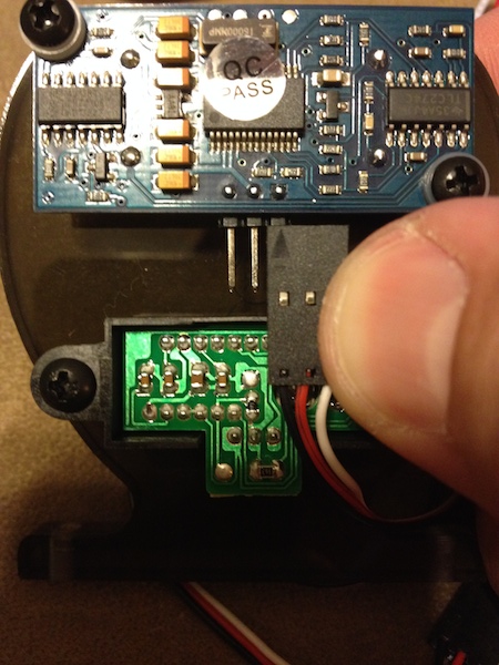
I just received two of the dual Ping/IR Sensor and stand modules. I am having an issue connecting the wire to the bottom of the Ping module.
Following the documentation for the "Dual Ping/IR Acrylic Stand with Sensors" it links to a download for only the IR stand. I followed the following for the IR portion:
http://www.parallax.com/sites/default/files/downloads/725-28995-SharpIRStand-v1.0.pdf
Then this for the Ping portaion:
http://www.parallax.com/sites/default/files/downloads/725-32008-Acrylic-Ping-Stand-v1.0.pdf
Both seemed to have the correct parts required, however once finished there is no way to get the cable on the Ping header.

I took the smaller of the two spacers out of the IR and put them on the Ping but that didn't work out too well, reducing the IR spacers anymore makes the white connector sit on the base so it aims down and is putting pressure on the connector/PCB rather than the standoffs.
Looking at the stock image below, my Ping module is slightly different (Above the center IC there is a different component) and the gap is different between the two sensors as it looks like the most of the connector wire fits between where mine only half fits.. Did something change on the stand or Ping module that is not allowing the connector to fit or is there a trick in the missing combo product documentation?

Following the documentation for the "Dual Ping/IR Acrylic Stand with Sensors" it links to a download for only the IR stand. I followed the following for the IR portion:
http://www.parallax.com/sites/default/files/downloads/725-28995-SharpIRStand-v1.0.pdf
Then this for the Ping portaion:
http://www.parallax.com/sites/default/files/downloads/725-32008-Acrylic-Ping-Stand-v1.0.pdf
Both seemed to have the correct parts required, however once finished there is no way to get the cable on the Ping header.
I took the smaller of the two spacers out of the IR and put them on the Ping but that didn't work out too well, reducing the IR spacers anymore makes the white connector sit on the base so it aims down and is putting pressure on the connector/PCB rather than the standoffs.
Looking at the stock image below, my Ping module is slightly different (Above the center IC there is a different component) and the gap is different between the two sensors as it looks like the most of the connector wire fits between where mine only half fits.. Did something change on the stand or Ping module that is not allowing the connector to fit or is there a trick in the missing combo product documentation?

450 x 600 - 122K
450 x 600 - 113K
Comments
-Phil
1. Pull off the black plastic using needle-nose pliers.
2. Using the pliers again, bend all three pins at the same time back around the PCB until you can put the extension cable on.
Note that after bending you shouldn't ever bend them back: too much bending will result in the pins breaking.
You might also be able to move the IR a bit closer to the acrylic by sanding down the white standoffs that it sits on.
If you're handy with a soldering iron you could flip the header around as well.
That might work, but the cables would be sticking up above the mount and be harder to hide, I went with this dual version to keep things nice and neat. Was hoping I was just missing something simple.
I actually already tried this, I took the smaller of the standoffs out to use on the Ping but when I went to put the IR back with just the single large standoff the white connector on the PCB hits the base first, so either you have to leave it really loose or tighten the screws down and put all the pressure on the PCB rather than the standoffs.
The product page links to the wrong manual and I cannot find the correct one, so I just used the individual product manuals to get the standoffs correct. Looking at the distance the Ping module needs to be moved back I would need much longer standoffs and longer screws as I really cannot add anymore standoffs with the current screws.
Was hoping there was a way to do this without voiding the warranty on the Ping or physical modification. The product photo shows its possible. I cannot find any other threads where people have had problems with this and its been out for over a year. Figured it had to be something I missed.
Yeah sorry was not comparing the Ping to the SR04 but just the way the connector was attached.
They were out of stock when I bought them for a week so not sure if there was an error in this new batch or if I had the standoffs wrong. Looking at it more tonight it seems I have the standoffs correct and it might be a part change or something.
I wonder if someone changed the pattern without testing to see if the cables still connected correctly?
Did you buy the stand and both sensors from Parallax? I see you've already emailed them (a good idea IMO).
As others have mentioned, there's several possible workarounds but you shouldn't have to do that with Parallax stuff. I hope you let us know how this turns out.
All the items came as a kit (The IR, Ping and Stand)
http://www.parallax.com/product/725-28998
Yeah I sent them an email with this thread for more info... Last night I figured it might have been something I was doing wrong so figured I would use the community first before bothering them.
However, on the two stands i received, the screw holes for the Ping device do not line up properly. I am only able to utilize the bottom right screw... the top left screw hole is way off...
How long ago did you order? Just wondering if its a recent issue. Someone suggested that, but I didn't want to risk damage to the PCB by bending pins.
Thanks, Ken Gracey
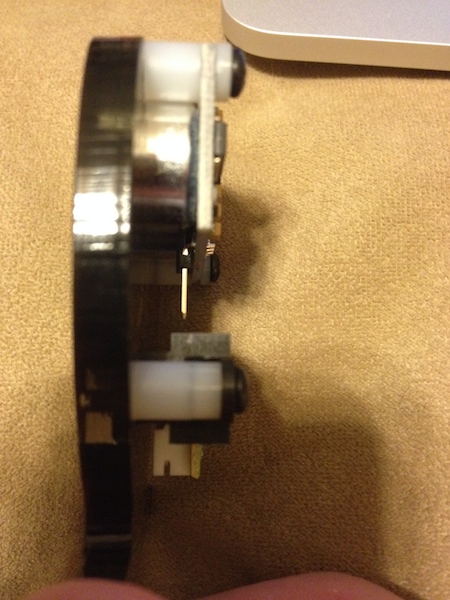
What we don't show is the side view (nor do we describe the tactic in the doc).
Simply bend the pins on the PING))) slightly outward as shown here...
Sorry for the confusion...
By doing it this way, we're able to significantly cut down on the overall height of the PING/IR stand assembly.
-MattG
As far as documentation, The product doc linked in the store is not for the dual sensor stand, nor can I find a dual sensor stand document anywhere.
That link has now been corrected and the proper documentation is there now.
Thanks!
-MattG
True, however then his eyes would be below his mouth. As he stands right now, he's "snorting" out an upside down light bulb. "Cute" wins don't it? :thumb:
-MattG
That document would have helped avoid my initial confusion, just didn't want to screw anything up. I changed this thread to solved. Thanks for the help. Looking forward to getting Arlo up and running now.
Dave
Just got them a few days ago. My understanding was that these were backordered, so this must be a new batch.
Yeah I would be interested, I heard a Eddie replacement board might be in the works but went with the Activity Board/HB-25 route. I am just starting out and looked at this a long time ago and finally decided to jump in. I have not done much coding on it yet, I looked at the Eddie files just to get an idea of some general things with how the encoders interact with the motor drivers. I have worked with Spin/PASM on another project I've done so started down that path. I'll check out the Propeller C but my goal for this was to learn more Spin/PASM for my other project.
Dave
For the most productive Propeller control we still recommend Spin/PASM, but the C examples could also be used simply to verify your test platform.
Personally, I prefer the HB-25/Activity Board route for Arlo. Once you've gotten past the wiring challenges for the HB-25s the Propeller Activity Board provides a load of great I/O devices and if you want it, the C compiler support.
I've attached an IR/WAV/Arlo project in C from Stephanie. This high-level program was written by Stephanie in the short part of a late afternoon just to prove the concept after Andy had spent a day or two porting the ActivityBot abdrive to arlodrive. This code isn't out there yet, but will be a future Insider post about how you can run ActivityBot code in an Arlo. What's really nice about this zip is the arlodrive.c files. We haven't written encoder support for this robot in Spin, I believe.
Thanks! I will check it out, always looking for references.
I think (Now I might be wrong) that the latest zip file posted on the Eddie product page has support for the new encoders. I have noticed when trying to figure out how to wire the encoders that there have been several versions, some having direct interaction to the HB-25. In the end I think I have it figured out, each encoder is running back to the Activity Board for 4 connections, then 1 connection out to the first HB-25 and than out of that and to the second. I spent the weekend making new connection cables for the encoders and HB-25's to get them all wired up so almost there. I will have to find time in the next week to try out the file you provided to do a full test of the system before I jump into the Spin/PASM stuff.
Dave
So I wired everything up like the ActivityBot, looking at the AlroDrive.c it ignores the 2nd encoder feed from both sides. I ran the calibration command in following the learning documents but it hardly moves, about 1/2 turn in each direction then a 1/4 turn in each direction. After that I ran a simple program to move forward and backwards and it only moved the left side wheel.
The calibration driver was not included so I used abcalibrate.h, was this reworked for Arlo?
Thanks,
Dave
You able to give a hint on timing of the post? Just wondering if its weeks or months out. I tried out this again and had the same issue. I drafted up some Spin/PASM code to test out the encoders this weekend to make sure they are working as I noticed in another thread for the Eddie platform this was their problem. I'll probably just go down my original path of Spin/PASM but for now just make a few small test applications to test each part to confirm its working.