

Tandem Bike Blinker Project

The general idea here is to build a directional signaling indicator that can be used when myself and my wife are riding our tandem bicycle in the evening.
I'm alway concerned about being ran over by a car comming up from behind us.
I've started this project thread to help me document the building of this device.
I've completed some breadboard circuits and used my Propeller Quickstart board to test if this was possible.
I was able to blink LED's on the Quickstart board the way I wanted them to work.
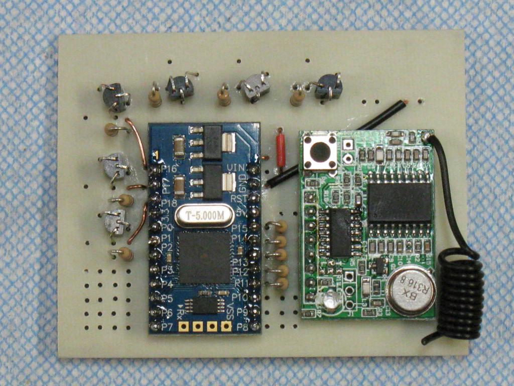
I took one step forward in purchasing Parallax Propeller-mini, 4-directional Tilt Sensors, XTR-MFET mosfets, Key Fob Remote and a few other bits.
I attempted to use Eagle Cad to design a circuit board but became somewhat impatient with myself
in the amount of time it took to learn how to do this.
SO
I took one step backwards to something I was more familiar with.
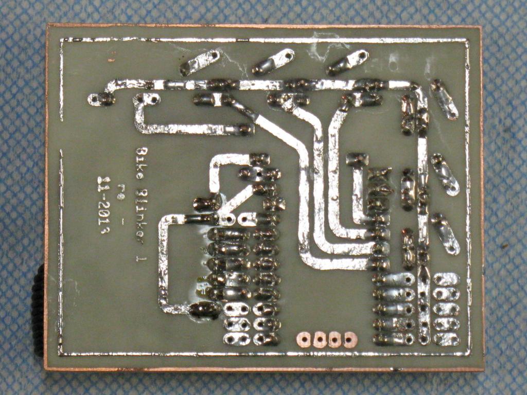
I did a circuit board drawing using my old AutoCad program and Toner transfer method to fabricate
a prototype board.
The following photos are the end result of where I am so far.

I think I would have been better off continuing on my Eagle Cad journey, but I could not resist trying out something that
I came up with concerning the toner transfer method of circuit board building.
I sprayed 4 coats of PVA release agent that I use on my fiberglass projects, onto Photo paper.
I ironed the printing onto my board and etched it.
End result was ok, I think, but my circuit traces are very much too wide.
The PVA really improved the transfer process.
As I'm developing this project, Any comments are always welcome.
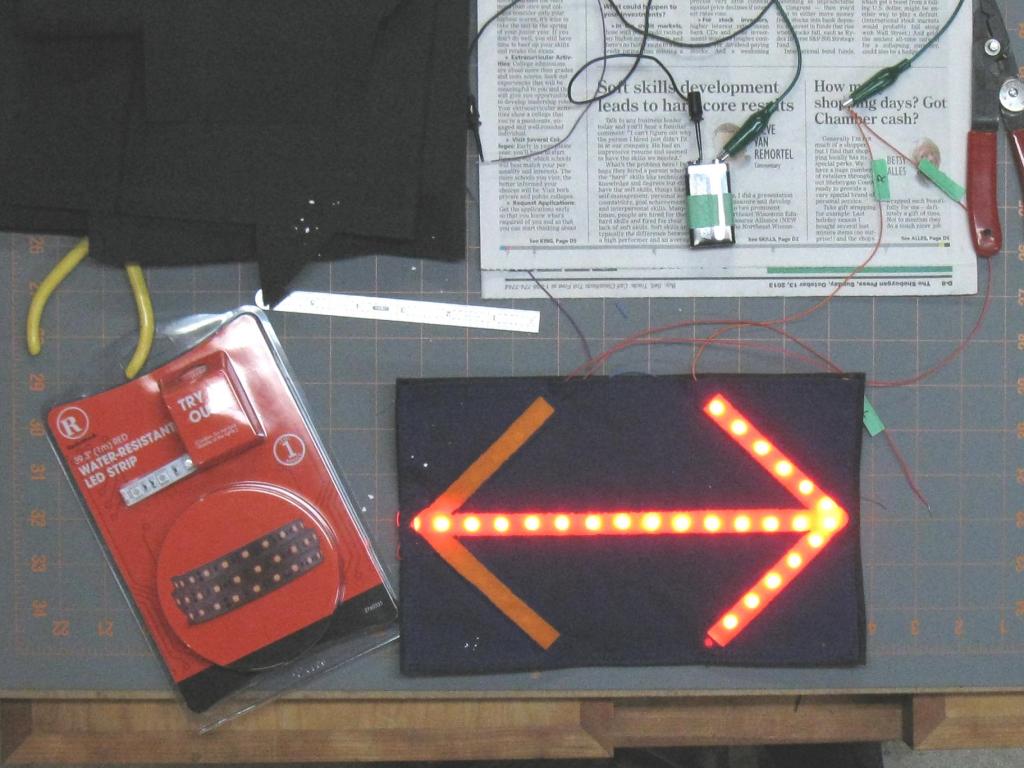
The next photo is from my original prototyping of this idea.

I'll reserve a couple of posts for future developments.
That's all I have for now.
Thanks
Garyg
I'm alway concerned about being ran over by a car comming up from behind us.
I've started this project thread to help me document the building of this device.
I've completed some breadboard circuits and used my Propeller Quickstart board to test if this was possible.
I was able to blink LED's on the Quickstart board the way I wanted them to work.
I took one step forward in purchasing Parallax Propeller-mini, 4-directional Tilt Sensors, XTR-MFET mosfets, Key Fob Remote and a few other bits.
I attempted to use Eagle Cad to design a circuit board but became somewhat impatient with myself
in the amount of time it took to learn how to do this.
SO
I took one step backwards to something I was more familiar with.
I did a circuit board drawing using my old AutoCad program and Toner transfer method to fabricate
a prototype board.
The following photos are the end result of where I am so far.
I think I would have been better off continuing on my Eagle Cad journey, but I could not resist trying out something that
I came up with concerning the toner transfer method of circuit board building.
I sprayed 4 coats of PVA release agent that I use on my fiberglass projects, onto Photo paper.
I ironed the printing onto my board and etched it.
End result was ok, I think, but my circuit traces are very much too wide.
The PVA really improved the transfer process.
As I'm developing this project, Any comments are always welcome.
The next photo is from my original prototyping of this idea.
I'll reserve a couple of posts for future developments.
That's all I have for now.
Thanks
Garyg

1024 x 768 - 128K
1024 x 768 - 128K
1024 x 768 - 99K
Comments
When fabricating my Prop-Mini and Key Fob Remote, my thinking was that the 3.3V regulator should be enough
to power my Key Fob Remote.
Over the next week or so, I'll be concentrating on some spin programming of the Mini.
I have not as of yet, applied power to my circuit.
Are there any opinions concerning using the Propeller Mini voltage regulator circuitry to power my
Key Fob Remote?
While breadboarding this, my Key Fob Remote appeared to be only drawing about 5ma current at 3.3volts.
All my resistors are 10K ohms and output transistors are mosfets.
Even though I'm committed to this, and will more than likely see what happens over the next week or so,
I could use a word of encoragement or discoragement.
No matter what happens, I'll post it on this thread.
Thanks
I was able to free up a couple of hours to power test my circuit board.
The Key Fob remote is being powered directly off the Prop-Mini 3.3V pin.
I connected my VOM using the 200ma setting for monitoring current.
When I turned on my 4AAA battery power supply, the VOM said overload, so I turned it off.
I went over the trace side of my circuit board with my 30x magnifier again and found a direct short to
ground due to a solder bridge.
I removed the solder bridge and reconnected my VOM and applied power.
Now I'm drawing only 16.2ma current.
That is pretty much in line with what I was expecting.
I think I need to have my 6v power connected when I attempt to program the Prop-Mini.
My next step will be to refine my Blinker spin program and attempt to load it.
I'll be doing my Blinker refinements using my Quickstart board and once it appears to be working there,
I'll attempt to load it on the Prop-Mini and find out if I burned something with my previously short circuit or not.
Thats all for now.
a multimeter before powering up! Ten seconds of time well spent I reckon.
Good luck...
This exactly why I posted the somewhat failure of my blinker project.
After building the circuit board, I checked for shorts with mulitmeter several times.
I also checked with my magnifer.
Somehow, I missed the shorted trace.
After checking the data sheet for the Prop-mini 3.3 regulator, It appears that it's somewhat tolerant of short circuits.
While I don't exactly understand all of the data on the data sheets, I'm very happy with the end result.
I think that by using the miliamp function on my VOM, I maybe saved this circuit.
Open circuits are very easy, Short circuits are always difficult for me to find before letting out the smoke.
I updated my lack of progress or actual progress.
I became disenchanted with the actual look of my wearable patch.
For now at least, it appears that the circuitry is working correctly and I'm attempting at getting the
physical look of this project to match my image.
This is actually much more difficult than I had imagined for such a seemingly simply project.
I've been pacing back and forth in my shop, staring at my various attempts at getting this thing to be what I
want it to be.
Today, I actually was able to start laying out a pattern and sewing my current image as to how this thing will look.
I think that over the next several days, I may actually have something fabricated that, in some manner matches my original project intent.
I'll post an update, when I actually have something worthwhile to share.
Thanks for anyone's interest.
gg