Shop OBEX P1 Docs P2 Docs Learn Events
Guess what I'm working on. (Revealed: Spinneret Web Server 2.0) — Parallax Forums

Guess what I'm working on. (Revealed: Spinneret Web Server 2.0)

David CarrierDavid Carrier Posts: 294
edited 2015-03-19 17:01 in Propeller 1
I'm ordering prototype PCBs for a new product I'm developing, and I realized it's rare that I've gotten this far into development without posting on the forums and seeking feedback. Rest assured that it incorporates lots of input from forums members, but there was enough preemptive feedback that I didn't have to ask any specific questions. I want to see if the design has met everyone's expectations, so I'm going to perform a test to see if it's up to it.

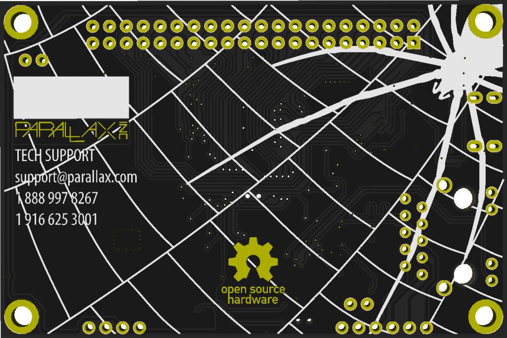
I have attached a rendering of the back side of the new product's PCB. Tomorrow I'll post the front side and a list of all of the features and capabilities. Until then, post what you think it is and what features you think it has. There are some obvious clues and some subtle clues in the rendering, but there are also some features that are not apparent from the image alone.

— David Carrier
Parallax Inc.
1024 x 684 - 129K
«13

Comments

  • jmgjmg Posts: 15,173
    edited 2013-11-06 13:59
    For a new Prop board, it seem starved of connectors ? ( or is it just a slave card ? )

    Any new design surely should have a rPi IO connector footprint included ?
  • David BetzDavid Betz Posts: 14,516
    edited 2013-11-06 14:09
    jmg wrote: »
    For a new Prop board, it seem starved of connectors ? ( or is it just a slave card ? )

    Any new design surely should have a rPi IO connector footprint included ?
    Looks like a Spinneret board for the QuickStart judging from the graphics.
  • NWCCTVNWCCTV Posts: 3,629
    edited 2013-11-06 14:29
    Wi Fi Spinnernet?
  • Duane DegnDuane Degn Posts: 10,588
    edited 2013-11-06 14:32
    David Betz wrote: »
    Looks like a Spinneret board for the QuickStart judging from the graphics.

    I second David's nomination.

    An ethernet add on card for the QuickStart.
  • MicrocontrolledMicrocontrolled Posts: 2,461
    edited 2013-11-06 14:55
    The 2 mounting holes near the bottom right and the 10 pin output makes me think this is for an Ethernet adapter... the Spinnernet graphics confirm that this is very likely what it is.
  • David BetzDavid Betz Posts: 14,516
    edited 2013-11-06 16:57
    There are some obvious clues and some subtle clues in the rendering, but there are also some features that are not apparent from the image alone.

    — David Carrier
    Parallax Inc.
    I'm not sure I can see any subtle clues for this but I'm hoping that this board has a SPI flash chip on it as well as the Ethernet interface and SD card. :-)
  • bomberbomber Posts: 297
    edited 2013-11-06 17:03
    It seems like a spinneret, but with the form factor and 40 pin GPIO header at the top...maybe it is spinneret 2.0? with 2 props?
  • WBA ConsultingWBA Consulting Posts: 2,934
    edited 2013-11-06 17:12
    I'm with bomber. A Spinnerete add-on in a Quickstart format would be nice, but you have the real estate to make it a Quickstart Spinnerette so that is my vote/hope.
  • David BetzDavid Betz Posts: 14,516
    edited 2013-11-06 17:28
    I'm with bomber. A Spinnerete add-on in a Quickstart format would be nice, but you have the real estate to make it a Quickstart Spinnerette so that is my vote/hope.
    You mean something like a QuickStart board with the touch buttons replaced by the Ethernet circuitry? Would there be enough room for an SD card slot as well?
  • Phil Pilgrim (PhiPi)Phil Pilgrim (PhiPi) Posts: 23,514
    edited 2013-11-06 17:38
    I, too, am guessing a Spinneret add-on for the QS. I hope the 40-pin connector is a stackable pass-thru, since I'm sure you don't need all 32 port pins for the Spinneret part.

    -Phil
  • David BetzDavid Betz Posts: 14,516
    edited 2013-11-06 17:42
    NWCCTV wrote: »
    Wi Fi Spinnernet?
    Wi-Fi would be cool! It would play well with the idea being discussed in another thread about programming a Propeller from an iPad.
  • GordonMcCombGordonMcComb Posts: 3,366
    edited 2013-11-06 17:51
    Spiders. Why did it have to be spiders.

    (With apologies to Indiana Jones.)

    Anyway, as with my others, my dime is on a Spinneret board for the QS. And I second Phil's request for stackable headers.
  • WBA ConsultingWBA Consulting Posts: 2,934
    edited 2013-11-06 19:17
    David Betz wrote: »
    You mean something like a QuickStart board with the touch buttons replaced by the Ethernet circuitry? Would there be enough room for an SD card slot as well?
    Yes, exactly. There is room to put the spinnerrette into a Quick start format including the SD.
  • David BetzDavid Betz Posts: 14,516
    edited 2013-11-06 19:20
    Yes, exactly. There is room to put the spinnerrette into a Quick start format including the SD.
    Even including my SPI flash chip? :-)
  • jmgjmg Posts: 15,173
    edited 2013-11-06 19:22
    David Betz wrote: »
    Even including my SPI flash chip? :-)

    Quad SPI, of course ?
  • David BetzDavid Betz Posts: 14,516
    edited 2013-11-06 19:33
    jmg wrote: »
    Quad SPI, of course ?
    I'd settle for a plain old SPI flash chip.
  • localrogerlocalroger Posts: 3,451
    edited 2013-11-06 20:10
    As I'm working through Season 3 of Babylon 5, I'd guess you've found a way to use a Propeller and this add-on to replace human telepaths as the operating system for Shadow attack ships. Way to compromise Earth Force security, dude.
  • WBA ConsultingWBA Consulting Posts: 2,934
    edited 2013-11-06 22:39
    David, Yes, you could funnel all that in. It may be a little snug, require some tricky routing or even going to 4 layer, but is definitely easy to do. The pic is my Quickstart Origin layout (from this thread) with the Ethernet conector, uSD socket, and Wiznet chip dropped in to get an idea of the available space.
  • Roy ElthamRoy Eltham Posts: 3,000
    edited 2013-11-07 01:59
    This is obviously a spinneret sequel in the form factor of the QuickStart. If you look at the traces and holes you can deduce a few things. First it's got the ethernet jack and a power over ethernet module hole pattern with traces leading to the jack's pins. Then it has all pins on the 40 pin connector wired up, with most of the traces leading to a central area on the board which is likely where the Prop is at (the traces leading from the 40 pin connector to the central area look very similar to the ones on the back of the QuickStart board). The wiznet chip is likely directly behind the jack. I'm guessing there is a USB connector next to the ethernet jack. Also guessing that there is a clock chip either in the upper left near the two pin holes there, or down between the ethernet jack and the power over ethernet module holes where there are two more pin holes (the clock chip has the int1 and int2 lines).

    There's also a square arrangement of vias in the lower left area. Usually that's done to allow heat through, right? Maybe some kind of regulator or something?

    Since it has the quickstart connector, you don't need to have a super lot built in to the board, you can just plug in something like the human interface board and or the memory card board.
  • mindrobotsmindrobots Posts: 6,506
    edited 2013-11-07 02:14
    Woo hoo!! We're getting a QuickWiz!!!!
  • AribaAriba Posts: 2,690
    edited 2013-11-07 03:27
    Here is my Guess of the front side.
    The WiFi is more a wish, I don't think it is really there.
    620 x 400 - 27K
  • Mike GMike G Posts: 2,702
    edited 2013-11-07 03:38
    Maybe we'll see a W5500 on the board? The W5500 buffers can be used as general purpose RAM.
  • David BetzDavid Betz Posts: 14,516
    edited 2013-11-07 04:38
    I guess we'll find out today what David is up to! Many of these guesses sound interesting.
  • Phil Pilgrim (PhiPi)Phil Pilgrim (PhiPi) Posts: 23,514
    edited 2013-11-07 08:11
    I'm still thinking plug-in for the QS. An RJ45 socket is quite high -- too high for a daughterboard to plug into a standard-height header socket without having a cutout to accommodate it. If this is the main board, the 40-pin socket will have to be elevated.

    -Phil
  • David BetzDavid Betz Posts: 14,516
    edited 2013-11-07 08:14
    I'm still thinking plug-in for the QS. An RJ45 socket is quite high -- too high for a daughterboard to plug into a standard-height header socket without having a cutout to accommodate it. If this is the main board, the 40-pin socket will have to be elevated.

    -Phil
    If that's the case, won't the height of the RJ45 also prevent using a stacking connector to allow another QS module to plug in on top of the Spinneret module?
  • Phil Pilgrim (PhiPi)Phil Pilgrim (PhiPi) Posts: 23,514
    edited 2013-11-07 08:22
    David Betz wrote:
    If that's the case, won't the height of the RJ45 also prevent using a stacking connector to allow another QS module to plug in on top of the Spinneret module?
    Yes, 'same potential issue.
  • TubularTubular Posts: 4,702
    edited 2013-11-07 11:46
    I'm guessing it's a PoE powered quickstart, using a silvertel PoE module along that bottom edge, eg
    http://www.silvertel.com/poe_products.htm#Ag8000

    I
    f it is, it will be very useful. Nice work, thanks David

    You can get elevated headers easily enough - PC104 also uses a 40 pin elevated header.

    edit: actually probably the newer and cheaper Ag9700 - http://www.silvertel.com/poe_products.htm#Ag9700
  • Alex.StanfieldAlex.Stanfield Posts: 198
    edited 2013-11-07 15:55
    The lower left side has a big fill area/gnd plane like if it had to make room for a big module. What can it be?

    Alex
  • David CarrierDavid Carrier Posts: 294
    edited 2013-11-07 17:38
    Roy Eltham is right on:
    Roy Eltham wrote:
    This is obviously a spinneret sequel in the form factor of the QuickStart. If you look at the traces and holes you can deduce a few things. First it's got the ethernet jack and a power over ethernet module hole pattern with traces leading to the jack's pins. Then it has all pins on the 40 pin connector wired up, with most of the traces leading to a central area on the board which is likely where the Prop is at (the traces leading from the 40 pin connector to the central area look very similar to the ones on the back of the QuickStart board). The wiznet chip is likely directly behind the jack. I'm guessing there is a USB connector next to the ethernet jack. Also guessing that there is a clock chip either in the upper left near the two pin holes there, or down between the ethernet jack and the power over ethernet module holes where there are two more pin holes (the clock chip has the int1 and int2 lines).

    There's also a square arrangement of vias in the lower left area. Usually that's done to allow heat through, right? Maybe some kind of regulator or something?

    Since it has the quickstart connector, you don't need to have a super lot built in to the board, you can just plug in something like the human interface board and or the memory card board.

    The clock chip is even right where he predicted, in the upper-left corner when viewed from the back. The two holes are for INT1 and INT2.

    The only correction is that you cannot connect a Human Interface Board or Propeller Memory Card. As Phil Pilgrim pointed out:
    An RJ45 socket is quite high -- too high for a daughterboard to plug into a standard-height header socket without having a cutout to accommodate it.
    Not only is it physically incompatible with a Human Interface Board, the built-in circuitry uses half of the Propeller I/O pins, so it is also electrically incompatible. It will work with the QuickStart Proto Board if it is set up in an overhanging configuration. All of the I/O pins are connected to the header, but half are used by the built-in hardware. P0 through P15 are untouched and available for use on the QuickStart Proto Board or any purpose-built boards.

    Don't worry about the inability to connect a Propeller Memory Card, because David Betz's hopes are true:
    David Betz wrote:
    I'm hoping that this board has a SPI flash chip on it as well as the Ethernet interface and SD card. :-)

    A latching microSD card socket and Quad SPI flash device share an SPI bus and the WIZnet device has its own SPI bus. It doesn't have dedicated SPI SRAM, but Mike G brought up a good point:
    Mike G wrote:
    Maybe we'll see a W5500 on the board? The W5500 buffers can be used as general purpose RAM.
    It does ahve a W5500, so you can use any unused buffer space as general-purpose SPI SRAM.

    Back to the real-time clock, instead of a supercapacitor, it has a socket for a CD-2032 battery. It takes up about 20% of the left side of the board (again when viewed from the bottom) and that is why it is mostly empty there. The PCB space does double as a heatsink for the 3.3 volt regulator, which will have to dissipate a bit more heat than the QuickStart did, because Ethernet circuitry can draw a few hundred milliwatts of power.

    As a few of you noticed, there are solder points for a Silver Telecom PoE module. It will have to go on the underside of the board, because the top side is too full. The board also has the newer FT231X USB controller, so it can also draw power from a USB charger.

    As for the name:
    bomber wrote:
    maybe it is spinneret 2.0?
    bomber was right: we're calling it the Spinneret Web Server 2.0

    As prommised, I have attached a rendering of the top side, as well as a placement diagram.

    — David Carrier
    Parallax Inc.
    1024 x 681 - 118K
    980 x 610 - 19K
  • David BetzDavid Betz Posts: 14,516
    edited 2013-11-07 18:01
    A latching microSD card socket and Quad SPI flash device share an SPI bus and the WIZnet device has its own SPI bus. It doesn't have dedicated SPI SRAM, but Mike G brought up a good point:

    It does ahve a W5500, so you can use any unused buffer space as general-purpose SPI SRAM.
    Nice! Thanks for including the flash chip! To be honest, the XMMC memory model is the most efficient of the PropGCC XMM models. If you can live with 32k of hub memory minus however much you allocate for cache then XMMC is the way to go.
Sign In or Register to comment.