

current detector with led power on
 Fovakis
Posts: 8
Fovakis
Posts: 8
Hi to all !
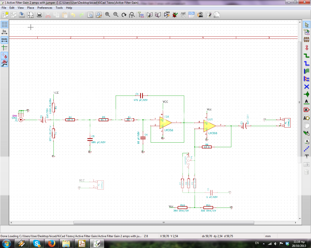
I have this 3 pole filter in my receiver's last stage. I want to put a led, so when the current is passing through my circuit the led will light on. I need this because my transmitter a lot of time, don't work fine, so i don't know if there any signal going to my receiver.
It is a way to check it.
Any ideas for cheap consuption ?http://i1284.photobucket.com/albums/a578/fovos1/Circuit_zpsb91f9e29.png
Comments
What is the power supply voltage used in the circuit?
I am thinking to put the transistor for example at the output of the active filter. I DON'T want to loose huge amount of Voltage output from the transistor because at the voltage output is the signal that i must transfer. any idea of the topology of this transistor? BJT or FET ? Common emitter maybe? i am a beginner ! thanks a lot
okk kwinn you are professional! tha's exactly what i wanted to do. Many thanks for that really!
What is the max current that led circuit "keep","steal" from my output?
Also, where in google i can search for that topology to understand why you put the devices in that order? it has any name?
Many thanks for that !