ADC08831 reading automotive throttle position
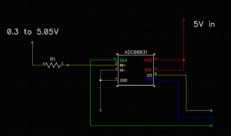
As the title says, I am attempting to read the throttle of a vehicle using the ADC08831. Here is the datasheet : http://www.ti.com/lit/ds/symlink/adc08831.pdf I am currently using an RC circuit that works, but is not accurate enough since it has a quite jumpy reading. All I need is to convert the reading of the ADC chip to a steady 0 to 100% value. The output of the TPS on my vehicle is anywhere from 0.3V to 5.05V. Do I need a resistor from the TPS to the input of the ADC? I have found that if I don't have at least a 10K resistor on my current RC circuit, it "shorts out" my throttle signal from the ECU. I cannot have this with the new chip.
Here is a schematic from what I have figured out from researching.
Here is a schematic from what I have figured out from researching.


Comments
An RC circuit is designed for measuring a resistance or capacitance change but your sensor changes voltage so you need an ADC.
Take a look at Process Control which uses an LM34 with an ADC since the LM34 voltage varies with temperature as a reference.
Your RC circuit was "charging" directly off of the throttle signal, so it was sucking current and causing issues. An ADC input won't consume any appreciable current, so you should be able to use any series resistor you like. Alternatively, you could use an op amp as a unity gain buffer, providing virtually infinite input impedence. http://www.facstaff.bucknell.edu/mastascu/eLessonsHTML/OpAmps/OpAmp3Note1Buffer.html