CAT5e and signal
A US digital single ended encoder has info that states max cable lengths 6'. I have several hundred systems using these encoders with 20'minimum, some up to 35', one maybe 45'. All feed direct to two inputs (Quadrature) on a Propeller through a 1k. The signals are about 5V. At some point when the Prop came out, I remember there was a post about current limiting for 5v using a 1k, but I see other posts that state higher values, but that is another story and of no concern since I have never blown a pin with 5V and a 1k.
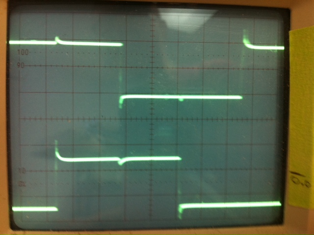
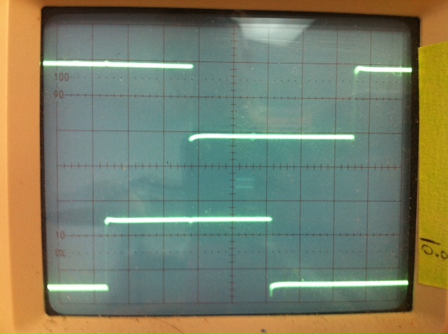
These are not high speeds, I would guess not even 2500 RMP at maximum. 400 lines. One image shows the scope looking at the encoder, with test leads at the encoder on the motor, using a 3' unshielded CAT5e. The other cable is 40' unsheilded CAT5. The spool the CAT5 is off is from a 100' Radio Shack stock. The spool clearly says CAT5, not CAT5e, I didn't think they even made CAT5 anymore, I assume that if it were CAT5e then the spool would say so.
I cannot detect any problems with the 40' length when running the motor, but have a project that will require several systems to connect with 40'. I have some single end to RS422 extender modules that US Digital sent, but they are a bit more work to add in.
Does anyone have an opinion on these signals to suggest a simpler method to clean up the difference you see on the 40'? Or. just leave it alone if it seems to be working? On the project, I intend to use CAT5e shielded and tie the drain to the chassis.


Comments
Pair 1
1 VSS
2 ENC A > 1KR > Prop input Quadrature Encoder Obj (5V signal)
Pair 2
3 VCC (5V)
4 ENC B > 1KR > Prop input Quadrature Encoder Obj (5V signal)
Pair 3
5 Hall1 6.25V signal to BLDC driver IC
6 Home Switch Sits at 5V
Pair 4
7 Hall2 6.25V signal to BLDC driver IC
8 Hall3 6.25V signal to BLDC driver IC
There is currently no termination, no caps on the encoder path, only the 1k limiting resistor at the Prop input.
You're getting a bit of glitching during the transition of the opposite channel. At the encoder, can you put a few hundred uF across Vss and Vdd to make sure the encoder power stays stable during switching?
At the Propellor, can you provide a bit of loading from A to Vss and B to Vss? Say 10K or so?
Cheers
-Phil
pass through that schmitt trigger gate. Since your signal of interest is of limited frequency you can afford to limit
its slew rate somewhat I think, and that should reduce spike amplitude (well it's worth trying and seeing.
What you are doing with pair 1 and 2 is what I meant by my post. I use that same wiring when I need to provide power the encoder, and add a 120 ohm resistor (or a 120 ohm resistor and 0.1uF in series) across each pair, and a 0.1uf and 10uF between Vss and Vdd.
Sorry, should have mentioned that when you provide power over the two pairs you need the 0.1uF capacitor in series with the 120 ohm resistors. For the Vss pair it's Vss to capacitor to 120 ohm to signal. For the Vdd pair it's Vdd to capacitor to 120 ohm to signal.