Curves, Propeller sourcing and sinking current.
 Tracy Allen
Posts: 6,667
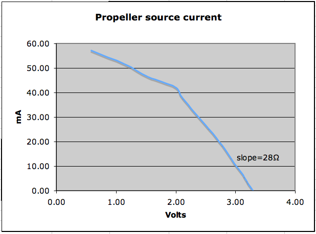
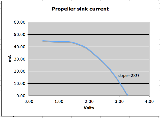
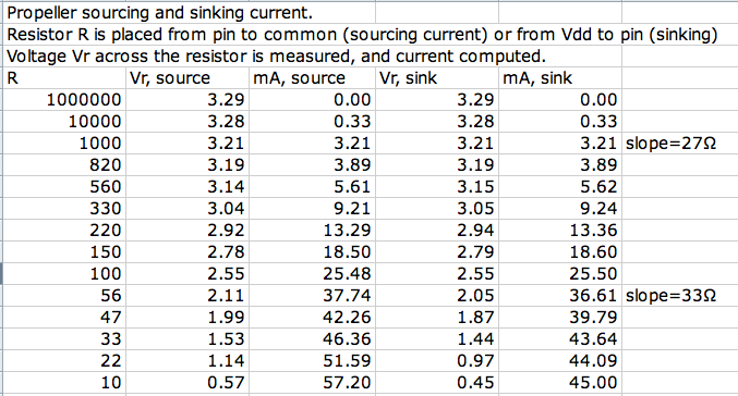
A recurring question is how to drive loads from Prop pins. For example, there was this thread, Multi-Color-LED-Question, where the question came up in the form of whether or not it would be safe to drive a blue, or green, or even a red LED, directly from a Prop pin without a limiting resistor. I threw out the figure of 30Ω as the output resistance of a Prop pin, but couldn't recall where I got that. We have lots of rules of thumb for this kind of thing, but it is worthwhile to have a reality check from time to time. I did a quick test using a demo board. Here are I/V curves for a pin, both sourcing current and sinking current. The slope of the line is the output resistance, that is, the equivalent circuit is 3.3V in series with this equivalent resistance. The slope of the curve changes with load, nonlinear. For loads up to 25 or 30 mA is close to 30Ω (varying from 27Ω at light loads to 33Ω at around 25mA). The source and sink curves track one another closely over that range. At heavier loads, the curves bend around to a limiting current and a higher equivalent resistance.


The surprise to me is the difference at higher currents, as it approaches a short circuit. Sinking bent around strongly toward 40mA, but sourcing was still heading up toward 60mA. Maybe Beau would have an explanation for that. I'm still used to thinking that n-fets could be counted on for more drive than p-fets.
The measurement at high currents is done with short durations. It is ambiguous, because the current and voltage drift as the internals heat up.


Comments
There is usually also a total package limit, which is often less than N * P mA
To me the curves show a P-FET that has been scaled to match the N-FET, but that also has poorer ideal 'curve tracer' transfer into the constant current region. So the higher P current is more because the N behaves like a better FET
The data sheet maximum is 40mA per pin, 300mA total for Vss or Vdd, and 1W for the package.