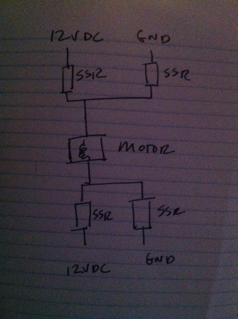
Recommend an SSR for this motor?
I need to rig up a 12VDC car lock motor for a gadget that must be extremely reliable. It will get used possibly anywhere from 10-30 times a day in short 1 second duration for many years to come. I have ruled out a relay since the arcing may degrade the contacts over time. I also prefer to just rig up something from off the shelf parts versus designing/making a board with a traditional hbridge high side and low driver driver/mosfet design. The plan is to drive the switch from a Propeller, one pin will turn on the 12VDC and GND for the motor to turn one direction, and another to reverse the motor. I was thinking about using SSRs for both high side and low side, but wanted to get your opinions on a robust way to do this. I believe the motor is pulling less than 1 amp.
This is an idea, but I would have to bump up the Prop output to turn it on:
http://www.skycraftsurplus.com/relaysolidstatedccontact.aspx?gclid=CLiHhMTa07kCFenm7Aod0XkAbg
or this will drive at 3 volts, assuming a single pin will provide the current for both, I need to check.
http://www.jameco.com/1/1/730-kf0604d-dc-dc-solid-state-relay-control-voltage-3-32vdc.html


Comments
3.3V logic is ok (VIH = 2.3V).
Repetitive pulse max = 2.5A = much more than you need.
Whichever version you get make sure and order a couple extra. I often have to redo some of the solder joints on these boards and more than a few haven't worked.
The L298N will lower your voltage by about 2V so make sure the lower voltage is okay.
I know a lot of people dislike the L298N for motor control. I suggest using a low PWM frequency if you do use PWM (I think I'm using 100Hz on my robots).
I haven't had any problem with driving the L298N with the Propeller's 3.3V logic which as already mentioned is above the required 2.3V.
This looks like the same thing basically, L298N available a mile away at the shack.
This is a first experiment with the L298. Can anyone suggest if it is possible to output some method of detection of measuring a higher current when the door lock motor has reached it's limit and stalled? It would be ideal if there was a method of feedback to check if the motor had reached the fully extended mode so that the Prop code can know that the lock had moved the gadget out of the way. I see some current sensing outputs, so maybe there is a way to rig up something to detect the higher current when the motor stalls.
To use them to sense current, I believe you need some low resistance high power resistors (not wire wound) so you can use an ADC to monitor the voltage drop across the resistors.
SparkFun has a datasheet on its L298N page.
What about some non-moving sensor? A magnet and Hall-effect sensor? Optical?
I think I've played with a Hall-effect sensor I purchased from Parallax once but I haven't done much with it.
I thought this part looked interesting.
I wonder if one of those photo interrupt sensors would work?