Automotive Pulse Generator reading on the Prop
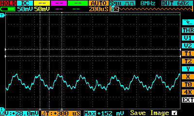
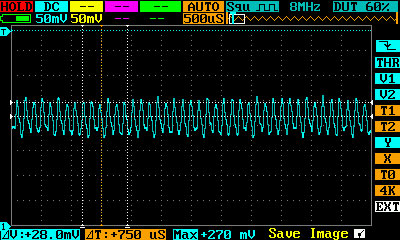
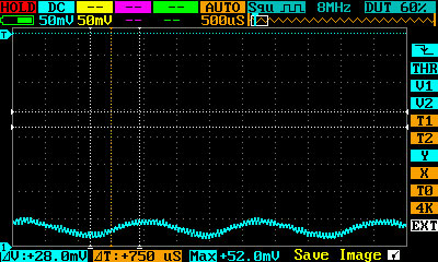
And yet another project.... I am trying to read a pulse generator that is located on the output shaft of my transmission so I can display the MPH on the parallax 2x16 display. First things first, I am not familiar with pulse generators and will probably need lots of help on this one. The only thing I know is most automotive pulse generators output an AC signal. I know the Prop cannot handle the AC signal and probably not the voltage, so before I go hooking it to a prop, I need to do some testing. The first thing I did was build an H-Bridge using some 1N4401 diodes, fed the pulse generator output to it, and hooked the O-Scope directly to the output of the H-Bridge. Here are some pics of the readings. Sorry I could not adjust the thresholds or other stuff on the images since I was driving. The Image1 is right around 45mph. The Image2 is around 100mph, and Image3 is about 10mph. What I am needing to do is somehow convert the pulse generator signal into a readable signal for the prop and calculate it into MPH. ALL help is appreciated!
EDIT : Changed images from BMP to JPG.
EDIT : Changed images from BMP to JPG.


Comments
Did you mean Full Wave Bridge? The images you posted do not look like a rectified ac signal.
This is what I mean by a full wave rectified signal....
Also, the voltage shown by the scope appears too low for a prop to work with. Possibly the diodes you are using are dropping a significant part. However...
I'm not so sure that messing with the input to the vehicle odometer is a good idea. After all, the odometer becomes a legal record if and when you sell the vehicle. And how can you insure that adding another circuit to the sensor output won't affect the reliability of the speedometer and odometer and adversely affect their accuracy?
IMHO I would leave the sensor alone and install another one somewhere on the driveline. A magnet and a pickup coil would certainly work after proper signal conditioning, such as an amplifier and a Schmidtt Trigger. That is what after market speed controls use.
AND driving at 100 MPH and tinkering with a scope!!!!! Your angels are working overtime.....
Hal
I was also thinking of making some sort of NPN / PNP transistor setup that will maybe output more of a usable wave that could be processed through the jm_freqin code found in the forums.
BTW, I was driving fast, but only had to hit 1 button to take the snap shot
EDIT : Also... I have set up a bench testing unit to hopefully help me figure out how to make a clean signal into the prop. I have a DC motor with a small gear on the shaft with the pulse generator mounted very close to the teeth of the gear. I am using a torn apart drill trigger to adjust the speed of the motor. Now I don't have to drive 100 mph to get a reading!
"The LM1815 is an adaptive sense amplifier and default gating circuit for motor control applications. The sense amplifier provides a one-shot pulse output whose leading edge coincides with the negative-going zero crossing of a ground referenced input signal such as from a variable reluctance magnetic pick-up coil."
They are cheap, reliable and pretty much bulletproof in my use and misuse of them. Datasheet: http://www.ti.com/lit/ds/symlink/lm1815.pdf
I've successfully used them as crank angle sensors in 16000 rpm engines using a 36-1 wheel so they're quite fast and accurate.
Will the LM1815 just hook directly to the pulse generator and then to the prop and it work? If there is other circuitry, I am going to need help with that as well please.
EDIT ***. This is the readings directly at the Prop Pin.
The only temporally accurate part of the raw input is the zero crossing. The voltage of a VR sensor varies with speed, #1, and #2, the sensor and teeth are almost certainly not exactly aligned with each other so the voltage each tooth generates is slightly different so your derived pulses are going to be inconsistent. If you counted pulses over, say, 500 ms or so and determined speed that way you'd be much more accurate but now you have a lag in your data. Zero crossing detection is the cure for the inconsistency you're seeing. I'll send you my notes re the 1815 circuit when I'm back at the estate later tonight. They are simple to use, the datasheet has lots of info on modes you will not use. I think it was pulling 7,9 & 14 to ground and using a 10K resistor on the input that was the simple, reliable approach I use - but I'm probably incorrect (memory read error in my head!) and will follow up shortly.If TI is going to take a long time for the sample you can get the 1815 from diyautotune.com or I can send you one gratis - they are cheap and I'm more than happy to support a fellow motor enthusiast!
-Mike
EDIT *** When watching it on the O-Scope, the square waves are not spaced evenly while driving a constant speed. The spacing jumps a little.
A good one that allows variation of gate/update time, and you can see the effect of average over time.
That will also give you scale values needed.
With any sensor like this, expect significant 'pattern jitter', but long term averages will be correct.
What update rate do you need, for your measurements ? - the longer you can tolerate, the less jitter you will get.
What info you you want out ? - just vehicle speed ? - and for the driver to read, or for other controls to use ?
Does the driver react to this, (ie do something different) or is it just to 'see how you are going' ?
If you wanted to gather more data, you could store a time-stamp of every edge, and then process that to give a fitted acceleration profile. Because you know the profile shape, that can be used to improve filtering.
A latching hall sensor should give nice square pulses.
The sensor is turned on by a magnetic south pole, and off by a magnetic north pole. So you'll need to install at least two magnets on the driveshaft, but you could install 4 or 6 or 8 to get better resolution. You'll need a pulse every inch traveled to get 0.001sec resolution at 60MPH. (60MPH = 1056 inches/second).
If you get a good clean sensor signal, I think the rest will be easy.
This looks like it would work https://www.sparkfun.com/products/9312
Bean
You can AC couple this and I would avoid the diodes. The scope plots show some high freq ripple, which should be reduced in a LPF, and then some hysteresis added to the slice point.
You know the maximum speed, and the lowest practical speed, so can filter quite aggressively.
Something like the MCP6544 has low power, Hyst inbuilt and is not too fast.
If you are looking for a simple setup to read your VR sensor then you should look in your local junk yard for a GM 7/8 pin module from an HEI distributor. The modules are already weather tight have easy to obtain connector hookups and convert the VR signal into a Square wave signal to drive a Tach which would be great for what you need. All you need are the P and N Inputs from the sensor then R is the output to the Tach. I am not sure if you need Battery + to the + terminal and Battery Negative to the mounting hole to power the unit or not. The unit new are only like 30 dollars or so. Good luck!