

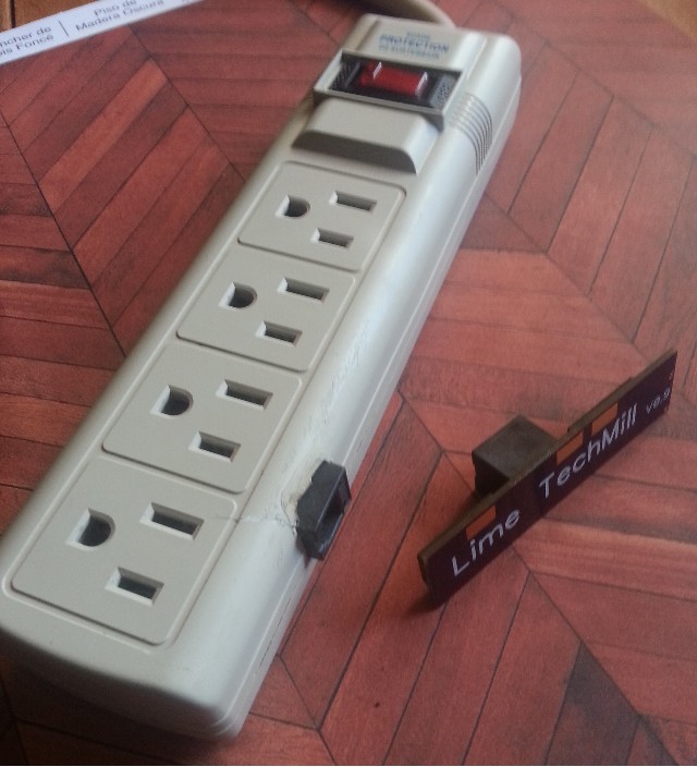
Dual SSR inside a PowerStrip

Step1: Cheap $4 power strip from Harbor freight
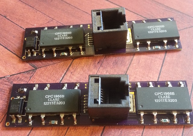
Step2: Solder pcb board with CPC1966B (3Amp up to 240 VAC) SSR's
http://www.mouser.com/Search/ProductDetail.aspx?R=CPC1966Bvirtualkey56550000virtualkey849-CPC1966B
and PS2505L-1-A Transistor Output Optocoupler (for mains hertz detection)
http://www.mouser.com/Search/ProductDetail.aspx?R=PS2505L-1-Avirtualkey55120000virtualkey551-PS2505L-1-A
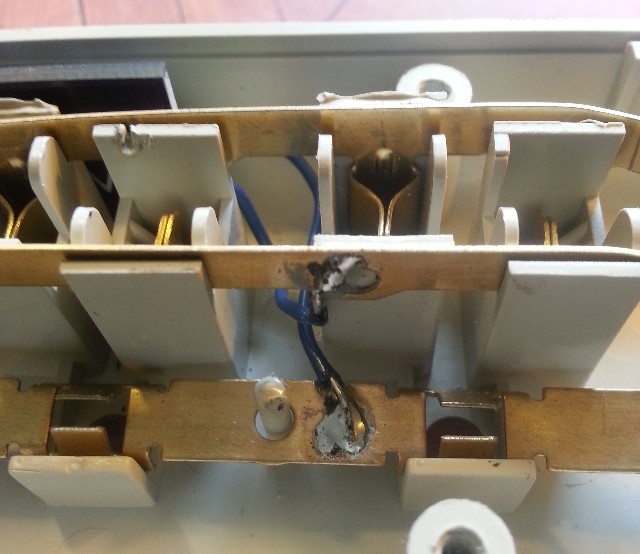
Step3: Cut the copper bar inside so it line up with the pads on the back of pcb. cut a hole in plastic for RJ12 6P SMT JACK
http://www.mouser.com/ProductDetail/Molex/85513-5002/?qs=%2fha2pyFaduikdRnLaL3shAQxtW4zSBwt9i32RLDmj%2fQ%3d
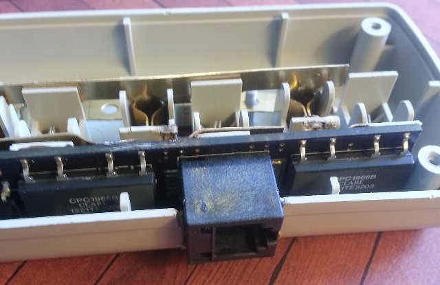
Step4: Solder pcb to copper strips inside power strip and also attach Neutral (only used for Opto) and Earth to pcb.
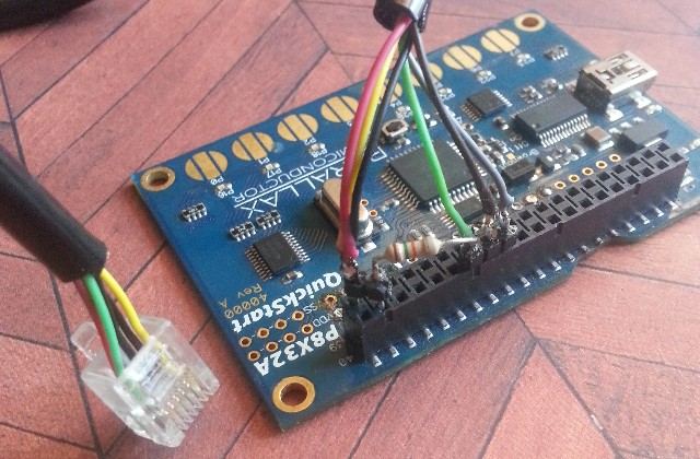
Step5: Control the signal with a Prop or Stamp , put a pull-up (~10k) on the Hertz detection pin it will be a 1 for short period during the cross over.
The SSR have zero-cross turn-on circuitry, so it will not go on right away but at next zero cross.
I tried to get dimming by using the added hertz detection and then a slight waitcnt and turn off the SSR, but no-go as the SSR must also have zero-cross turn-off.
You could toggle on/off after each cross over, but 30hz does have visual flicker even on incandescent bulbs so the hertz detection is only good to detect that main power is on.
Step2: Solder pcb board with CPC1966B (3Amp up to 240 VAC) SSR's
http://www.mouser.com/Search/ProductDetail.aspx?R=CPC1966Bvirtualkey56550000virtualkey849-CPC1966B
and PS2505L-1-A Transistor Output Optocoupler (for mains hertz detection)
http://www.mouser.com/Search/ProductDetail.aspx?R=PS2505L-1-Avirtualkey55120000virtualkey551-PS2505L-1-A
Step3: Cut the copper bar inside so it line up with the pads on the back of pcb. cut a hole in plastic for RJ12 6P SMT JACK
http://www.mouser.com/ProductDetail/Molex/85513-5002/?qs=%2fha2pyFaduikdRnLaL3shAQxtW4zSBwt9i32RLDmj%2fQ%3d
Step4: Solder pcb to copper strips inside power strip and also attach Neutral (only used for Opto) and Earth to pcb.
Step5: Control the signal with a Prop or Stamp , put a pull-up (~10k) on the Hertz detection pin it will be a 1 for short period during the cross over.
The SSR have zero-cross turn-on circuitry, so it will not go on right away but at next zero cross.
I tried to get dimming by using the added hertz detection and then a slight waitcnt and turn off the SSR, but no-go as the SSR must also have zero-cross turn-off.
You could toggle on/off after each cross over, but 30hz does have visual flicker even on incandescent bulbs so the hertz detection is only good to detect that main power is on.
Comments
It's not a safe design if you don't have full isolation to your controller. From your description of the AC sense I suspect you are tapping neutral as a reference. Bad design!
No I don't, neutral is only used on the high-voltage-side of the opto-insolator
You can not drive ±160v in series with a 47K resistor (use 100K for 220V) parallel-LED without ground (e.g neutral)
I could also used earth, but even tiny 4mA is frown on as earth is only emergency ground.
Check out data sheet.
http://www.mouser.com/ds/2/286/ps2505-34260.pdf
The SSR are are "highside" switches and don't need neutral at all.
MCU Vss goes to the board but is never mixed with neutral or earth.
I will put up schematic soon.
Link Below is Zip file with Schematic and Dip file (and 3D models)
Warning: 115AC is dangerous!
https://onedrive.live.com/redir?resid=6D7787B33D967B1A%214163
inside it could kill you? It's usual to have 0.5" spacing and/or a routed slot in the PCB between dangerous and low-voltage sides for this and
other reasons (such as condensation). The easiest fix for this is to pot up the high voltage parts of the circuit in epoxy so nothing can touch them.
Brown = Mains
Green = Earth ground
Blue = MCU traces.
Solder mask is a pretty good insulator, so the only high volt part on the pcb's topside that are open to the air is the 8 upper pins and small pads.
I can see I did not tent the via's on this side, that is a good idea to do.
Due to size limit imposed probably not the best spacing.
Should move down the Rj12 connector a little, so the Earth barrier would be complete.
Soldermask is not mains rated to my knowledge, I wouldn't trust my life to something like that.
Could also plug it in to a GFCI outlet for extra protection.
Updated it a little, with a different connector 12.5 mm creap should be possible.
I think 1.6mm pcb thinkness is OK?, as there is mains on the other side that is pretty close to connector.
And maybe it's better not to Earth Ground the PCB?
8mm looks like the recommended