

BS2 + PBASIC + Easy Stepper Motor Driver + ripped motor from old HDD ...
 wperko
Posts: 66
wperko
Posts: 66
Hi,
New to putting stepper motors to work ... the idea is to learn this enough so that I might be able to make some neat visual art projects with movement and lights etc... Later maybe design a new D.A.I.R. for stepper motors a little beefier than a hobby servo motor.
But I don't know what I'm doing ... yet!
My program that got the motor turning, but isn't under very good control ... now I need to know what I'm doing wrong ... for instance ... why doesn't the motor turn reverse when I send the low to the DIR pin?
I'm using this basic wiring to a Parallax HomeWork Board for starters; http://bildr.org/blog/wp-content/uploads/2011/05/EasyDriver-Stepper-Motor-Driver2-400x722.png
' EasyStepperDrive-02.bs2
' {$STAMP BS2}
' {$PBASIC 2.5}
' BS2 Pins to Easy Driver Pins
' P0 - Dir
' P1 - Step
' P2 - MS1
' P3 - Sleep
' P4 - MS2
' Vss to Gnd on Easy Stepper Motor Driver
' Vin to M+ on Easy Stepper Motor Driver
' Vdd to +5V on Easy Stepper Motor Driver
' Declare Variables
i VAR Word
' Main Body
DO
GOSUB stepforward
PAUSE 500
'GOSUB stepbackward
LOOP
END
' Subroutines
stepforward:
FOR i = 0 TO 10
HIGH 0
HIGH 1
HIGH 0
LOW 1
NEXT
RETURN
stepbackward:
FOR i = 0 TO 50
HIGH 1
HIGH 1
HIGH 1
LOW 1
NEXT
RETURN
END
The second motor is a BiPolar Stepper motor with each wire pair separate from the other wire pair and about 4Ω on each pair.
This motor reactions are not so much different than the other motor ... the Brushless Stepper seems more controllable, but from further study on the net it seems to need a different kind of motor controller ... still I can't get the Easy Stepper Motor Drive to control the BiPolar stepper motor as I want. It does respond better with PWM inputs to the STEP pin on the Easy Stepper Motor Drive, but I need to know more;
From what I can see in the demos, the Step pin uses a PWM input … in PBASIC that's:
FOR I = 1 TO (Steps?)
PULSOUT (BS2 Pin1 connected to STEP Pin on EasyDriver), (how many pulses?)
PAUSE (how many ms?)
NEXT
For the direction do I just toggle the DIR pin Logic 1 or 0?
For the MS1 and MS2 pins do I just toggle the DIR pin Logic 1 or 0?
For the Enable pin do I just toggle the DIR pin Logic 1 or 0?
For the RST pin do I just toggle the DIR pin Logic 1 or 0?
For the SLP pin do I just toggle the DIR pin Logic 1 or 0?
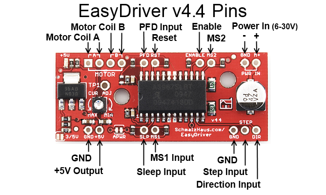
http://www.schmalzhaus.com/EasyDriver/EasyDriver_v44/EasyDriver_V44_Description.png
The D.A.I.R. project: http://www.brainless.org/DAIR-Kit.html
...
New to putting stepper motors to work ... the idea is to learn this enough so that I might be able to make some neat visual art projects with movement and lights etc... Later maybe design a new D.A.I.R. for stepper motors a little beefier than a hobby servo motor.
But I don't know what I'm doing ... yet!
My program that got the motor turning, but isn't under very good control ... now I need to know what I'm doing wrong ... for instance ... why doesn't the motor turn reverse when I send the low to the DIR pin?
I'm using this basic wiring to a Parallax HomeWork Board for starters; http://bildr.org/blog/wp-content/uploads/2011/05/EasyDriver-Stepper-Motor-Driver2-400x722.png
' EasyStepperDrive-02.bs2
' {$STAMP BS2}
' {$PBASIC 2.5}
' BS2 Pins to Easy Driver Pins
' P0 - Dir
' P1 - Step
' P2 - MS1
' P3 - Sleep
' P4 - MS2
' Vss to Gnd on Easy Stepper Motor Driver
' Vin to M+ on Easy Stepper Motor Driver
' Vdd to +5V on Easy Stepper Motor Driver
' Declare Variables
i VAR Word
' Main Body
DO
GOSUB stepforward
PAUSE 500
'GOSUB stepbackward
LOOP
END
' Subroutines
stepforward:
FOR i = 0 TO 10
HIGH 0
HIGH 1
HIGH 0
LOW 1
NEXT
RETURN
stepbackward:
FOR i = 0 TO 50
HIGH 1
HIGH 1
HIGH 1
LOW 1
NEXT
RETURN
END
The second motor is a BiPolar Stepper motor with each wire pair separate from the other wire pair and about 4Ω on each pair.
This motor reactions are not so much different than the other motor ... the Brushless Stepper seems more controllable, but from further study on the net it seems to need a different kind of motor controller ... still I can't get the Easy Stepper Motor Drive to control the BiPolar stepper motor as I want. It does respond better with PWM inputs to the STEP pin on the Easy Stepper Motor Drive, but I need to know more;
From what I can see in the demos, the Step pin uses a PWM input … in PBASIC that's:
FOR I = 1 TO (Steps?)
PULSOUT (BS2 Pin1 connected to STEP Pin on EasyDriver), (how many pulses?)
PAUSE (how many ms?)
NEXT
For the direction do I just toggle the DIR pin Logic 1 or 0?
For the MS1 and MS2 pins do I just toggle the DIR pin Logic 1 or 0?
For the Enable pin do I just toggle the DIR pin Logic 1 or 0?
For the RST pin do I just toggle the DIR pin Logic 1 or 0?
For the SLP pin do I just toggle the DIR pin Logic 1 or 0?
http://www.schmalzhaus.com/EasyDriver/EasyDriver_v44/EasyDriver_V44_Description.png
The D.A.I.R. project: http://www.brainless.org/DAIR-Kit.html
...
Comments
All the motors from hard drives I've seen were brushless.
It has 4 wires and it doesn't turn on a straight 5V DC or AC so I presume it is a stepper motor. When applying volts to a pair the motor STEPS and STOPS, then apply the voltage to the other pair the motor STEPS and STOPS. It is turning with the Easy Stepper Driver ... I just can't seem to figure out how to control speed, steps and direction yet. It does do a floppy kind of thing when I try to do slower steps with the FOR/NEXT loops ... but without any pauses it seems to spin medium speed and smoothly.
Pin1 - Pin2 = 1.3Ω
Pin1 - Pin3 = 1.3Ω
Pin 1 - Pin4 = 1.3Ω
Pin2 - Pin3 = 2.4Ω
Pin2 - Pin4 = 2.4Ω
Pin3 - Pin4 = 2.4Ω
Pin1 seems the common ... and this meets the basic criteria of a certain type of Stepper Motor.
See: http://forums.parallax.com/showthread.php/119874-Hard-Drive-Stepper-Motor-with-high-speed-spin-up-circuit
...
The second motor is a BiPolar Stepper motor with each wire pair separate from the other wire pair and about 4Ω on each pair.
This motor reactions are not so much different than the other motor ... the Brushless Stepper seems more controllable, but from further study on the net it seems to need a different kind of motor controller ... still I can't get the Easy Stepper Motor Drive to control the BiPolar stepper motor as I want. It does respond better with PWM inputs to the STEP pin on the Easy Stepper Motor Drive, but I need to know more;
From what I can see in the demos, the Step pin uses a PWM input … in PBASIC that's:
FOR I = 1 TO (Steps?)
PULSOUT (BS2 Pin1 connected to STEP Pin on EasyDriver), (how many pulses?)
PAUSE (how many ms?)
NEXT
For the direction do I just toggle the DIR pin Logic 1 or 0?
For the MS1 and MS2 pins do I just toggle the DIR pin Logic 1 or 0?
For the Enable pin do I just toggle the DIR pin Logic 1 or 0?
For the RST pin do I just toggle the DIR pin Logic 1 or 0?
For the SLP pin do I just toggle the DIR pin Logic 1 or 0?
I think first you need to set the diection once you enter your sub function, not each time through your for loop. Pin0 low to high transition for one direction, then high to low for the other direction. Also pay attention to the purposeful delays in the example, those are needed. Plus do more than 10steps, steps on a stepper are quite fine to the human eye, try a thousand steps so you can see movement.
But it still needs to be a stepper and not a brushless motor. (Though it can be argued a stepper is a brushless motor but I think a hard drive motor needs a different controller.)
Not a bad idea but it shouldn't matter. The direction pin will still stay either high or low either way.
I don't think this is required nor desirable. The Arduino code uses low to high in each direction.
Agreed but the 500ms pause should be plenty.
Agreed (sort of). I'd also suggest more than ten steps but a hundred or two should be plenty. Many (most?) stepper motor have 200 steps per revolution.
Again, all this applies to stepper motors not to brushless motors.