

Logitech Extreme 3D Pro Joystick Driver, Hack, Extras
 Keith Young
Posts: 569
Keith Young
Posts: 569

This is my initial post to really start this project I had started before. After graduating from Engineering school I have more time to devote to actual stuff, and when looking around for a project I found a giant pile of dust, under which was this joystick.
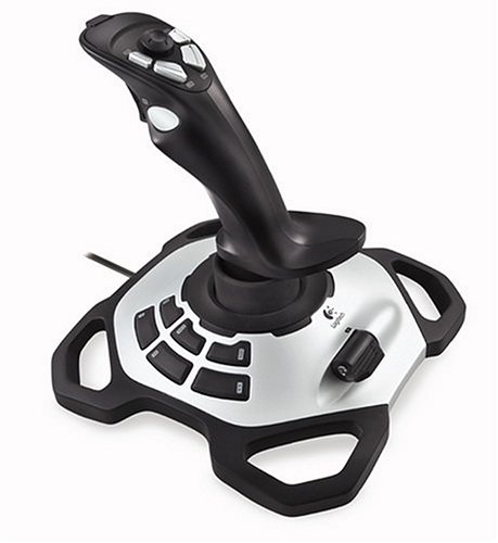
I've had this thing for years. It's a Logitech Extreme 3D Pro, and can be had for $30 bucks or so.
Amazon
I'll add more detail later, but essentially my buddy broke his and I managed to fix it, and realized how simple the design looked. I bought a new shinier joystick for gaming (Saitek) and started hacking the 3D Pro.
I took out the screws from the base, took out the circuit board that converts all the signals then sends it out a USB cable, and started figuring out how it worked. My most useful tool for this was Parallax's USB Oscilloscope.
Parallax
I found that there were fewer wires than buttons. It was accomplished by sending pulses up the wires. I managed to duplicate this system and then write it in Assembly code.
When writing down all the improvements I can make, I realized this was a large enough project to warrant a Project Thread.
Current to do list:
- Improve documentation
- Add calibration (in progress)
- PID or something to smooth the ADC data
- Make it easier to call the program externally
- Eventually use this for something cooler than controlling a cardboard box turned into an Ekranoplan
So anyway, this is just opening up the project. I don't have much on it yet, but I cleaned up my demo last night and will keep working on it.
OBEX Link
I do have an old YouTube video of an old version. I'll be making a better video in the future.
http://www.youtube.com/watch?v=XJqs5wlxxEY
This is my first project, so I'd love to have some input, especially about making this user friendly and well documented. I'll have 100 problems with this. My current one is when calibrating, sometimes the output will go over 65,536. Being a Mechanical/Aero Engineer I don't know much about WORD,LONG,FLOAT etc. So I need to figure out if I should leave a safety gap, or change the data type etc. I may as well post all the code below for now, since people tend to ask for it.
Thanks for the help and any comments/ratings. Please enjoy this object, help me make it better for you and others, and let others know if it works for you so they aren't afraid of spending $30 bucks on a dud.
{{
Keith Young - kyoung21@utk.edu
Updated - Jul 31 2013
Copyright (c) 2012 Keith Young
Terms of use at end of file
Instructions:
A basic schematic is shown below for how to get things set up.
Several examples are given for how buttons and analog signals can be used.
For now, the default I'm uploading is with the 6 base buttons on the joystick
commented out to improve the speed. This is because it's difficult to fit
all the wires without modifying the joystick through drilling or getting
special wires. It's totally easy and doable to make more space for the
wires, but the assumption is you don't want to do any more than remove the
circuit board inside and replace all that with wires going out to your Prop.
To enable these 6 buttons, go to the assembly code below and uncomment all
the code for the extra buttons.
I have several improvements in mind, but first I want to see how this better demo
does. I hope to get better documentation, calibration, and smoothing etc
in later versions.
I am new to uploading this sort of stuff, so please leave feedback for
recommendations, and especially let people know if this works for you.
I don't want people to be afraid of spending $30 bucks to get the
joystick and fear this won't work. So please comment and rate!
This assumes colors of wires are the same throughout the manufacturing
history of this product. You may wish to check this so as to be sure
you aren't connecting this bass ackwards.
Joystick -----------------------------------------------------------------
Red ┼ Pin 19 and Pull Up 3.3V (I use 10Kohm)
Green ┼ Pin 20 and Pull Up 3.3V
White ┼ Pin 21
Yellow ┼ Pin 22 and Pull Up 3.3V
Pink ┼ Pin 23 and Pull Up 3.3V
Orange ┼ Pin 24
Grey ┼ Pin 25
Brown ┼ 3.3V
Rudder Pot Black ┼ 1st Channel ADC
Blue ┼ GND
Red ┼ 3.3V
Aileron Pot Green ┼ 2nd Channel ADC
Elevator Pot White ┼ 3rd Channel ADC
Black ┼ GND
Joystick Base ------------------------------------------------------------
Orange ┼ Pin 15
Black ┼ Pin 14 and Pull Up 3.3V
Brown ┼ Pin 13 and Pull Up 3.3V
Grey ┼ Pin 12 and Pull Up 3.3V
Pink ┼ Pin 11 and Pull Up 3.3V
Yellow ┼ Pin 10
White ┼ GND
Throttle Pot Green ┼ 4rth Channel ADC
Red ┼ 3.3V
tk Basic ADC Schematic
tk link to website/blog
tk Calibration
tk PID or other smoothing
tk Easier to call the program from outside
http://www.amazon.com/Logitech-Extreme-Joystick-Silver-Black/dp/B00009OY9U/
https://www.youtube.com/watch?v=kAVJzw98xW4 (Old version not using PST)
Also note, skipping the base buttons you can fit the silver cover back on
without problems. When you want to include the 6 base buttons though
you'll probably need to drill a small hole or something to fit all those
wires out since the USB wire hole is too small.
}}
CON
_clkmode = xtal1 + pll16x
_xinfreq = 5_000_000
ADC_dpin = 1 'Sets ADC Pins
ADC_cpin = 2
ADC_spin = 0
rudderc = 0 'Sets ADC Channels
aileronc = 1
elevatorc = 2
throttlec = 3
baud = 115200
OBJ
AD : "MCP3208_fast_ADC"
DB : "FullDuplexSerial"
VAR
long Shared
word rudder, aileron, elevator, throttle
'Calibration
word ruddermin, ruddermax, aileronmin, aileronmax
word elevatormin, elevatormax, throttlemin, throttlemax
word rudderslope, rudderint
word aileronslope, aileronint
word elevatorslope, elevatorint
word throttleslope, throttleint
word rudderout, aileronout, elevatorout, throttleout
long stack[256]
byte Cog
PUB Start(Pos) : Pass
AD.Start(ADC_dpin, ADC_cpin, ADC_spin, 0) 'Start ADC
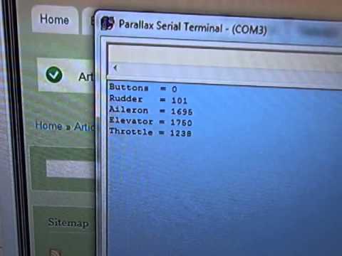
DB.Start( 31, 30, 0, baud) 'Start Parallax Serial Terminal communication
Pass := (Cog := cognew(@entry, @Shared)+1)>0'Begin running Assembly code
'It's where the actual sampling takes place
dira[27]~~ 'LED setup
outa[27]~
dira[26]~~
outa[26]~
Check 'Enter main loop
Pub Check
repeat 'Main user accessable loop
waitcnt(clkfreq / 20 + cnt) 'Slow down long enough to display on PST
rudder := AD.In(rudderc) 'Get ADC value of Rudder
aileron := AD.In(aileronc) 'Get ADC value of Aileron
elevator := AD.In(elevatorc) 'Get ADC value of Elevator
throttle := AD.In(throttlec) 'Get ADC value of Throttle
DB.Str(String(16))
DB.Str(String("Buttons = "))
DB.Dec(Shared) 'Display status of Buttons
DB.Str(String(13))
DB.Str(String("Rudder = "))
rudderout := rudderslope*rudder-rudderint
DB.Dec(rudderout) 'Display Rudder value
DB.Str(String(13))
DB.Str(String("Aileron = "))
aileronout := aileronslope*aileron-aileronint
DB.Dec(aileronout) 'Display Aileron value
DB.Str(String(13))
DB.Str(String("Elevator = "))
elevatorout := elevatorslope*elevator-elevatorint
DB.Dec(elevatorout) 'Display Elevator value
DB.Str(String(13))
DB.Str(String("Throttle = "))
throttleout := throttleslope*throttle-throttleint
DB.Dec(throttleout) 'Display Throttle value
DB.Str(String(13))
{{
The small section immediately below shows how the buttons can be used
in your code.
1 - If you pull the trigger, PST will show "Trigger Engaged", LED on
2 - If you press HAT forward right, PST will show "Combo Engaged", LED on
3 - If you press buttons 3 and 4 on Joystick, calibrate
4 - If throttle is high and button 2 is held...
}}
'1
if shared & butt1 == butt1
outa[27]~~
DB.Str(String("Trigger Engaged"))
else
outa[27]~
'2
if shared & butt13 == butt13 and shared & butt14 == butt14
outa[26]~~
DB.Str(String("Combo Engaged"))
else
outa[26]~
'3
if shared & butt3 == butt3 and shared & butt4 == butt4
DB.Str(String("Calibrate"))
Calibrate
'4
if shared & butt2 == butt2 and throttle > 2000
DB.Str(String("AFTERBURNER"))
Pub Calibrate
waitcnt(clkfreq + cnt)
ruddermin := rudder
ruddermax := rudder
aileronmin := aileron
aileronmax := aileron
elevatormin := elevator
elevatormax := elevator
throttlemin := throttle
throttlemax := throttle
repeat while shared & butt3 <> butt3 and shared & butt4 <> butt4
waitcnt(clkfreq / 50 + cnt) 'Slow down long enough to display on PST
rudder := AD.In(rudderc) 'Get ADC value of Rudder
aileron := AD.In(aileronc) 'Get ADC value of Aileron
elevator := AD.In(elevatorc) 'Get ADC value of Elevator
throttle := AD.In(throttlec) 'Get ADC value of Throttle
if rudder < ruddermin
ruddermin := rudder
if rudder > ruddermax
ruddermax := rudder
if aileron < aileronmin
aileronmin := aileron
if aileron > aileronmax
aileronmax := aileron
if elevator < elevatormin
elevatormin := elevator
if elevator > elevatormax
elevatormax := elevator
if throttle < throttlemin
throttlemin := throttle
if throttle > throttlemax
throttlemax := throttle
rudderslope := 65536/(ruddermax-ruddermin)
rudderint := rudderslope*ruddermin
aileronslope := 65536/(aileronmax-aileronmin)
aileronint := aileronslope*aileronmin
elevatorslope := 65536/(elevatormax-elevatormin)
elevatorint := elevatorslope*elevatormin
throttleslope := 65536/(throttlemax-throttlemin)
throttleint := throttleslope*throttlemin
waitcnt(clkfreq + cnt)
Pub Stop
if Cog
CogStop(Cog~ -1)
DAT
ORG 0
entry mov Mem, PAR
or dira,pinn21
or outa,pinn21
or dira,pinn25
or outa,pinn25
or dira,pinn24
or outa,pinn24
{{ or dira,pinn10 Un comment this area in order to use
or outa,pinn10 the 6 buttons on the base of the
or dira,pinn15 joystick and the throttle
or outa,pinn15
or dira,pinn17 ALL AREAS OF CODE COMMENTED OUT BELOW CONTROL
and outa,pinn17 JOYSTICK BASE. UNCOMMENT FOR THIS FUNCTION }}
or dira,pinn27
and outa,pinn27
xor outa,pinn21
xor outa,pinn25
xor outa,pinn24
'xor outa,pinn10
'xor outa,pinn15
mov time,cnt 'Current clock loaded into time
add time,delay 'delay added to time
:Loop
xor outa, pinn21 'Pin 21 PHASE 1
waitcnt time,delay
mov temp, ina
test temp, pinn23 wz '13 Hat Up
if_z or button, butt13
if_nz andn button, butt13
test temp, pinn22 wz '14 Hat Right
if_z or button, butt14
if_nz andn button, butt14
test temp, pinn19 wz '15 Hat Down
if_z or button, butt15
if_nz andn button, butt15
test temp, pinn20 wz '16 Hat Left
if_z or button, butt16
if_nz andn button, butt16
xor outa, pinn21
'--------------------------------------------------------------------
xor outa, pinn25 'Pin 25 PHASE 2
waitcnt time,delay
mov temp, ina
test temp, pinn20 wz '1 Trigger
if_z or button, butt1
if_nz andn button, butt1
test temp, pinn19 wz '2 Secondary
if_z or button, butt2
if_nz andn button, butt2
test temp, pinn22 wz '3 Bottom Left
if_z or button, butt3
if_nz andn button, butt3
test temp, pinn23 wz '4 Bottom Right
if_z or button, butt4
if_nz andn button, butt4
xor outa, pinn25
'----------------------------------------------------------------------------------
xor outa, pinn24 'Pin 24 PHASE 3
waitcnt time,delay
mov temp, ina
test temp, pinn20 wz '5 Top Left
if_z or button, butt5
if_nz andn button, butt5
test temp, pinn19 wz '6 Top Right
if_z or button, butt6
if_nz andn button, butt6
xor outa, pinn24
'-------------------------------------------------------------------------------------
{{ xor outa, pinn10 'Pin 10 PHASE 4
waitcnt time,delay
mov temp, ina
test temp, pinn12 wz '7 Base Top Left
if_z or button, butt7
if_nz andn button, butt7
test temp, pinn11 wz '8 Base Top Right
if_z or button, butt8
if_nz andn button, butt8
xor outa, pinn10
'------------------------------------------------------------------------------------
xor outa, pinn15 'Pin 15 PHASE 5
waitcnt time,delay
mov temp, ina
test temp, pinn13 wz '9 Base Middle Left
if_z or button, butt9
if_nz andn button, butt9
test temp, pinn14 wz '10 Base Middle Right
if_z or button, butt10
if_nz andn button, butt10
test temp, pinn12 wz '11 Base Bottom Left
if_z or button, butt11
if_nz andn button, butt11
test temp, pinn11 wz '12 Base Bottom Right
if_z or button, butt12
if_nz andn button, butt12
xor outa, pinn15 }}
wrlong button, Mem
jmp #:Loop ' Check trigger again using :loop
button byte 0000000000000
delay long 5000
pinn21 long |< 21
'pinn10 long |< 10
pinn25 long |< 25
pinn24 long |< 24
'pinn15 long |< 15
'pinn17 long |< 17
pinn27 long |< 27
pinn20 long |< 20
pinn19 long |< 19
pinn22 long |< 22
pinn23 long |< 23
'pinn12 long |< 12
'pinn11 long |< 11
'pinn13 long |< 13
'pinn14 long |< 14
butt1 long |< 0
butt2 long |< 1
butt3 long |< 2
butt4 long |< 3
butt5 long |< 4
butt6 long |< 5
' butt7 long |< 6
' butt8 long |< 7
' butt9 long |< 8
' butt10 long |< 9
' butt11 long |< 10
' butt12 long |< 11
butt13 long |< 12
butt14 long |< 13
butt15 long |< 14
butt16 long |< 15
temp long 0
time Res 1
Mem Res 1
{{ Obviously this is the license and not part of the base buttons. Leave this
commented out.
///////////////////////////////////////////////////////////////////////////////////////////////////////////////////////////////
// TERMS OF USE: MIT License
///////////////////////////////////////////////////////////////////////////////////////////////////////////////////////////////
// Permission is hereby granted, free of charge, to any person obtaining a copy of this software and associated documentation
// files (the "Software"), to deal in the Software without restriction, including without limitation the rights to use, copy,
// modify, merge, publish, distribute, sublicense, and/or sell copies of the Software, and to permit persons to whom the
// Software is furnished to do so, subject to the following conditions:
//
// The above copyright notice and this permission notice shall be included in all copies or substantial portions of the
// Software.
//
// THE SOFTWARE IS PROVIDED "AS IS", WITHOUT WARRANTY OF ANY KIND, EXPRESS OR IMPLIED, INCLUDING BUT NOT LIMITED TO THE
// WARRANTIES OF MERCHANTABILITY, FITNESS FOR A PARTICULAR PURPOSE AND NONINFRINGEMENT. IN NO EVENT SHALL THE AUTHORS OR
// COPYRIGHT HOLDERS BE LIABLE FOR ANY CLAIM, DAMAGES OR OTHER LIABILITY, WHETHER IN AN ACTION OF CONTRACT, TORT OR OTHERWISE,
// ARISING FROM, OUT OF OR IN CONNECTION WITH THE SOFTWARE OR THE USE OR OTHER DEALINGS IN THE SOFTWARE.
///////////////////////////////////////////////////////////////////////////////////////////////////////////////////////////////
}}
I will also be writing about this on my website at http://www.consultkeithyoung.com/content/projects/joystick.
459 x 500 - 27K
Comments
Let me know if this is a horrible idea. I may have stepped foot in a computer science building, but not much rubbed off on me.
free and the program in the computer is simple. I have made a Propeller object to read in the data. I have yet to take mine apart. I will be following your project. Have fun with your project!
I can definately make use of that in other projects. This project will still be necessary for me though since I need to not rely on a computer.
An update, when changing to 12 bit, the slope of my calibration curve is 1.5 so I'm having hassles. I'm looking in to F32, or another way around it since Spin seems to struggle with FLOAT variables.
This might be applicable to your project as far as fitting the range within a binary weighted value ...
http://forums.parallax.com/showthread.php/149231-DEMO-Succesive-Aproximation-Normalization-%28SAN%29-Filter
Thanks!