Help calculating torque required
Hi All,
I'm having a bit of trouble remember basic physics and hoping someone can help If i've got the wrong forum, please feel free to move/delete.
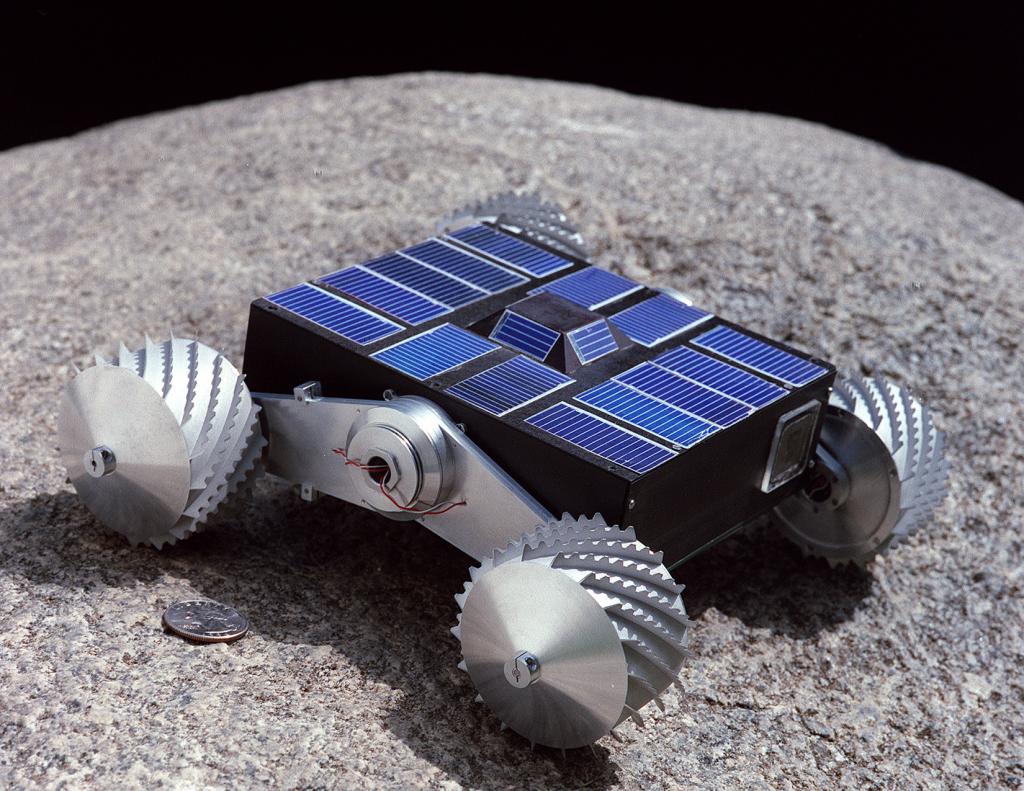
I'm designing a robot which resembles this one (Kind of, its a bit different but the basic forces etc would be the same so i've found this piturec for illustrative purposes)

The wheels are attached to struts which can rotate through 360 degrees around a central 'hub'.
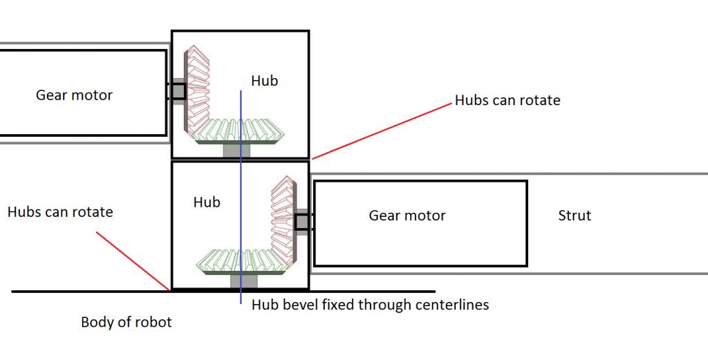
To rotate the struts, I intend to put a gearmotor in each strut, acting on a bevel gear within the hub. Excuse the paint drawing, but here is a plan view of one side of the robot.
Hope it makes sense, my CAD drawing is at home

My problem lies in selecting an appropriate sized gear motor with enough torque to lift the robot as i've come up with 2 possible results and im not sure which (if any) is right!
Assume the following.
-No energy lost due to friction
-Length of strut 150mm
-Radius of central bevel gears 40mm
-Weight of robot 4kg, all 4 wheels in contact with the ground, so weight in each wheel 1kg.
-Gear ratio of bevel 'gearbox' 4:1
Here is my first force drawing for a single strut. The strut needs to be rotate counter clockwise to lift the body of the robot.
Fe is the force provided by the motor acting on the bevel gear. Assume the motor providing the force weighs nothing.
Fl is the weight of the robot acting on 1 wheel.

De=40mm
Dl=150mm
Fl = 1 * 9.8 = 9.8N
Fe*De=Fl*Dl
Fe=(Fl*Dl)/De
I get Fe = 36.75Nm as a result, that's an awful lot of torque for a small gear motor!
My second line of though it just a simple lever, with Fl of 9.8N acting at .15m, and the gearmotor acting through an additional 4:1 ratio torque multiplier provided by the bevel gear.
This gives me a much nicer result of 1.47Nm / 4 = .36Nm.
The problem with this second solution is that im unsure of the effect of having the motor acting 40mm from the center, and not directly on the axis.
So my question is, are both of these results flawed? Have I got my force diagrams wrong?
Thanks in advance!
I'm having a bit of trouble remember basic physics and hoping someone can help
I'm designing a robot which resembles this one (Kind of, its a bit different but the basic forces etc would be the same so i've found this piturec for illustrative purposes)

The wheels are attached to struts which can rotate through 360 degrees around a central 'hub'.
To rotate the struts, I intend to put a gearmotor in each strut, acting on a bevel gear within the hub. Excuse the paint drawing, but here is a plan view of one side of the robot.
Hope it makes sense, my CAD drawing is at home

My problem lies in selecting an appropriate sized gear motor with enough torque to lift the robot as i've come up with 2 possible results and im not sure which (if any) is right!
Assume the following.
-No energy lost due to friction
-Length of strut 150mm
-Radius of central bevel gears 40mm
-Weight of robot 4kg, all 4 wheels in contact with the ground, so weight in each wheel 1kg.
-Gear ratio of bevel 'gearbox' 4:1
Here is my first force drawing for a single strut. The strut needs to be rotate counter clockwise to lift the body of the robot.
Fe is the force provided by the motor acting on the bevel gear. Assume the motor providing the force weighs nothing.
Fl is the weight of the robot acting on 1 wheel.

De=40mm
Dl=150mm
Fl = 1 * 9.8 = 9.8N
Fe*De=Fl*Dl
Fe=(Fl*Dl)/De
I get Fe = 36.75Nm as a result, that's an awful lot of torque for a small gear motor!
My second line of though it just a simple lever, with Fl of 9.8N acting at .15m, and the gearmotor acting through an additional 4:1 ratio torque multiplier provided by the bevel gear.
This gives me a much nicer result of 1.47Nm / 4 = .36Nm.
The problem with this second solution is that im unsure of the effect of having the motor acting 40mm from the center, and not directly on the axis.
So my question is, are both of these results flawed? Have I got my force diagrams wrong?
Thanks in advance!


Comments
Maybe I'm misunderstanding something here, but isn't your Fe supposed to be a force and not a torque?
That's probably where i'm going wrong. So how would I change this result into torque?
All I need to do is multiply the force required (36.75Nm) by the distance (0.04m) to get the required torque (1.47Nm)
Is this correct?
I'm sorry but I don't understand exactly what you are trying to do here. But in looking at only your simple drawing, the one you call "first force drawing for a single strut," here's what I'm guessing you have going on. First, I presume the fat black dot in your drawing is your pivot point. Next, it appears to me that you have 9.8 newtons acting at a distance of 0.15 meter from the pivot point. That would result in 1.47 newton-meters of torque acting clockwise (CW) around your pivot. To balance this 1.47 nm, you have force Fe acting at a distance of 0.04 meters from the pivot point, generating a torque acting in the counter-clockwise (CCW) direction.
To do your calculations properly, you need to keep your units straight. For example, your forces should be expressed only in newtons, not newton-meters. Torque is expressed in newton-meters.
So in your case, based on what I see in your drawing, Fe would be 1.47nm/0.04m = 36.75 newtons.
Again, I'm not sure what you are doing with your gears, etc. but I hope that helps. Also, I wouldn't totally forget about frictional forces: unless you've got excellent alignment, great bearings, etc. frictional forces can be substantial.
I'm going to have to rethink this a bit, physics is not my strong point!
Thanks for the help.
You will need force of 3.75kg on the large bevel gear to support 1kg at 150mm. The distance from the wheel to the fulcrum is 3.75 times the distance from the gear to the fulcrum.
Your gear motor has a bevel gear with a 10mm radius for a 4:1 ratio.
The force on the smaller bevel gear will be the same 3.75kg.
Your torque on the gear motor will be 3.75kg/cm, ignoring all losses of course.
The maximum torque you need would be calculated using the centerline of the wheel axis to the the centerline of the body mounted hub as your distance.
The force component is the weight of the robot / 4 since you have 4 wheels. However, this is undersized because it assumes each wheel will always share the load evenly. The slightest "tilt" of the robot on any surfaces shifts the vectors and 1 or more wheels would need to lift the weight of the robot + a portion of the weight of each of the 3 other struts/wheels. (I would plan on doubling the calculated torque to be on the safe side.)
Once you have this torque value, you can use ratios of the bevel gears for the torque required by the motor. So- if the length were 1 meter and the force applied by gravity were 10 newtons (for that strut), you'd need 10 nm of torque to raise the strut. As you approach a 45 degree strut angle (relative to horizontal) you'd need about half the torque to keep raising it.
Now- if your bevel gear were mountain radially about the centerline of the wheel axle, and it's radius from the centerline were 0.5m, you'd have to apply 10 nm of torque to that bevel gear to rotate the strut. Your distance is halved.... but your force component is doubled. Your motor would still need to provide 10 nm of torque, but the force component needs to be 20 n. That's where horsepower (watts) comes into play if you care to take it that far.
EDIT: Yeah, what these other guys are saying!
I like the sound of that because the result is exactly the same as my second solution! (3.75kg/cm = 0.36Nm)
BTW, Friction will come into play later. I plan on using a sprung washer and friction plates to hold the hubs and body together with enough force to keep the struts from moving due to gravity if the motors are turned off.
Its just a trade off between the amount of current required to move the struts considering the friction, vs the holding current required.
For now, i'm trying to see if I can provide enough torque to lift the robot, then see if I can provide enough to break that friction...
I knew 36Nm was too high! Funnily enough, my second solution was the first I though of, but I second guessed myself thinking it was too simple haha
W9GFO's solution proves my second one which is good enough for me.
Rforbes, regarding the angle thing. This is my worst case scenario, as you suggest torque requirement will drop as the robot raises
The motors I plan on using can produce around ~1.2Nm so we are miles in, giving me enough headroom even if 80% of the robot weight is on one wheel. Gives me confidence this friction thing might work out also.
There you go mixing your units of measure again! [noparse] :-) [/noparse]
Torque output from electric motors is measured in Nm, Oz-in, kgcm etc
Ahem, Nm, metric. Miles, imperial.