MAX6675 For Reflow Oven controller
Ok ,
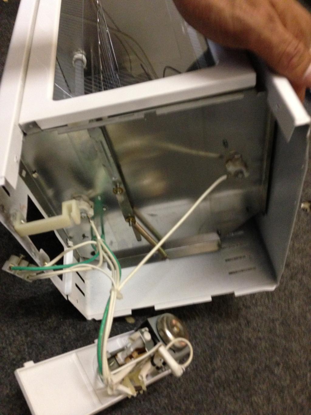
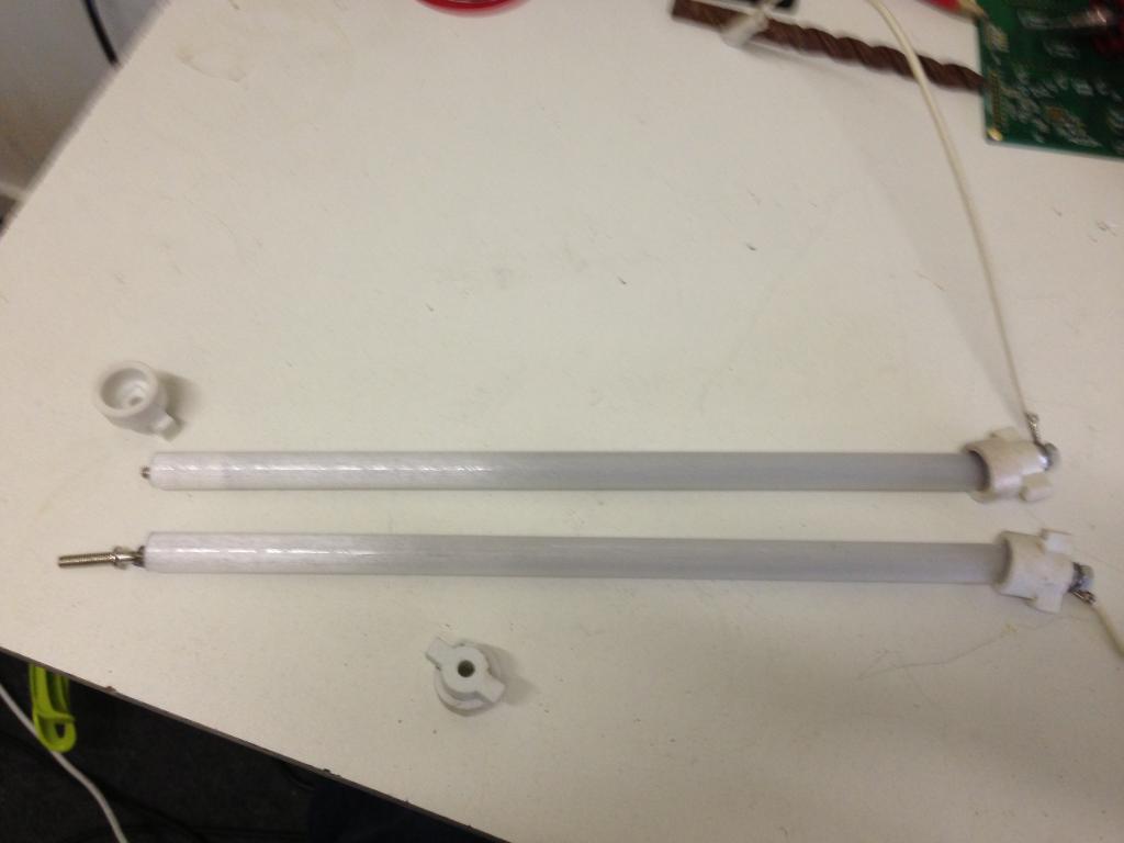
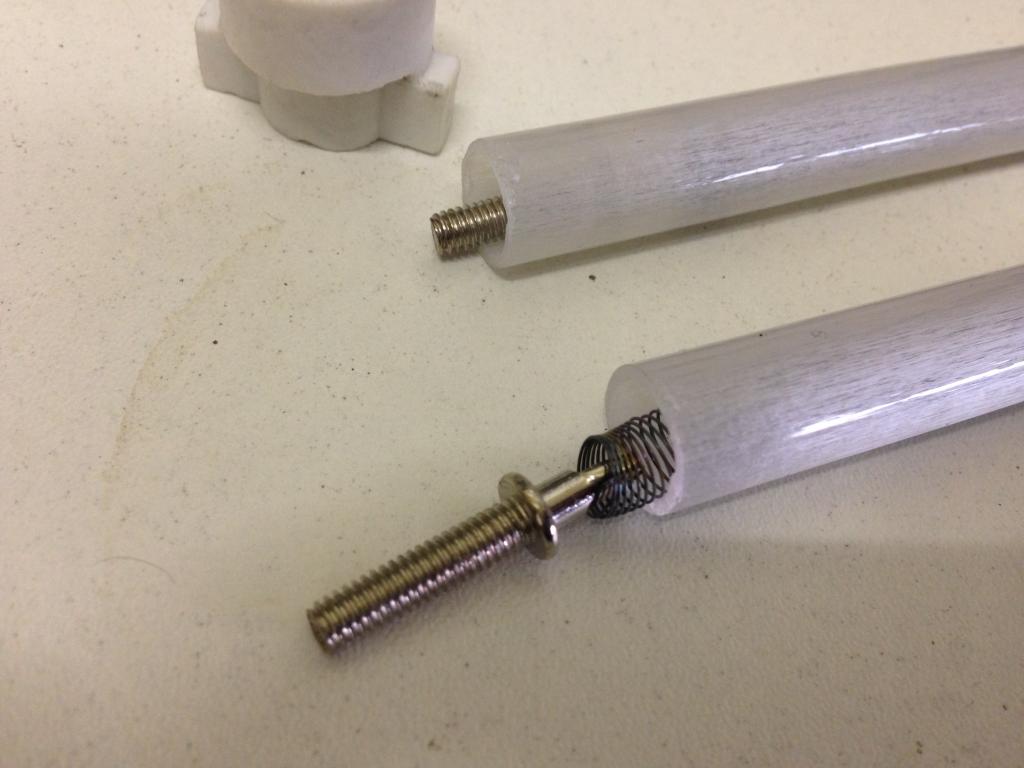
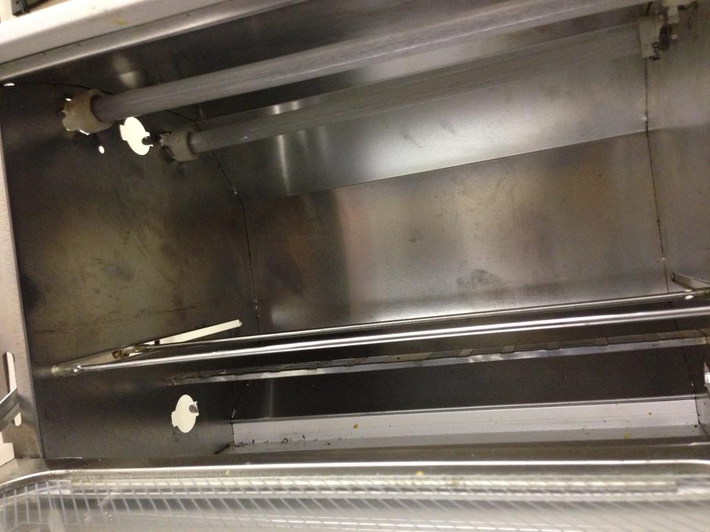
SO I am trying to build a small reflow oven controller, already have the oven ( a small 9liter model ) modified bringin both heating elements to the top , also a solid state relay to turn it on/off . ill figure pwm will have to do that later .
But for the moment I cant get to seem to get any temp readings out of the max 6675 ,
This is my second one , The first one , i think i blew it up by putting more then 5 volts acoss it by accident , but now the second ( these are not the cheapest ) is also not sowing me some love here
Anyone mind sharing a pice of code , I have tryied modifinig the one found in the obex(Mike Lord) that usualy works with a tv , but I need it to work on terminal to start with , after i got a 20X4 lcd already hooked and working . still no luck with it .
code used is below ,
Any help in the right direction would be greatly appriciated :P:thanks
Previeuw
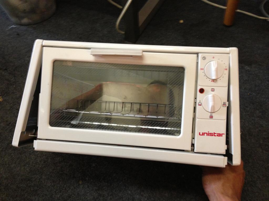
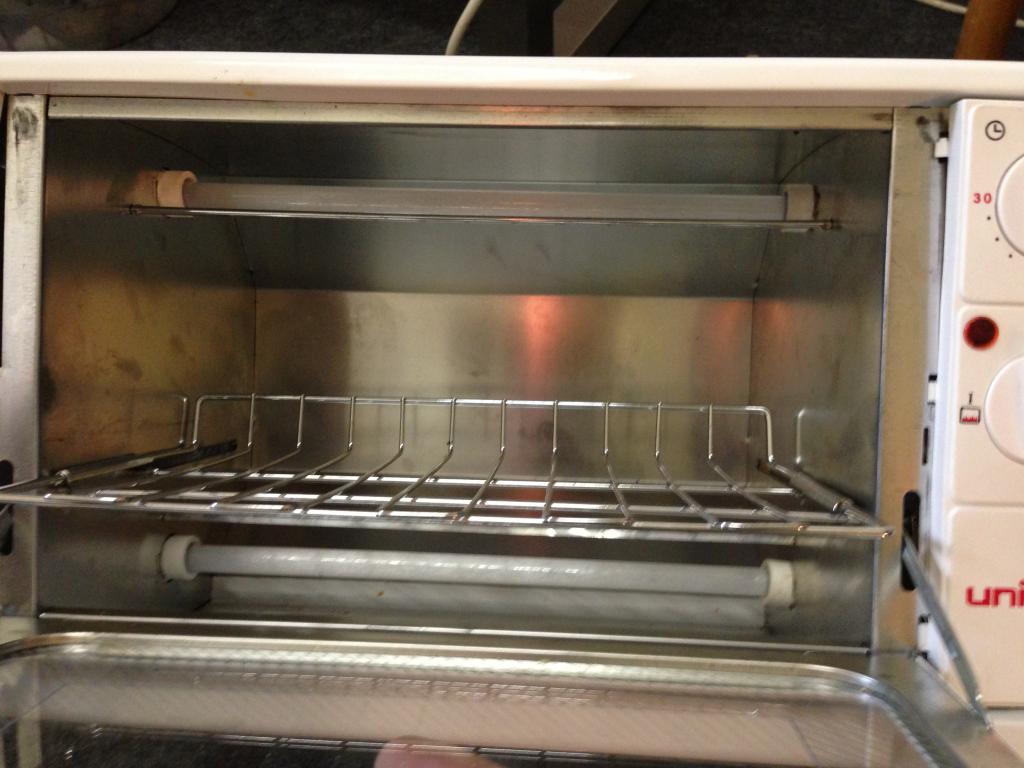
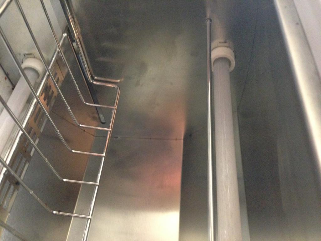
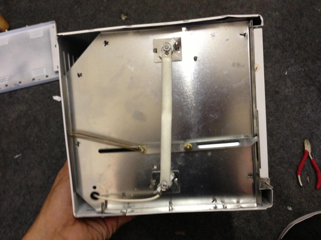
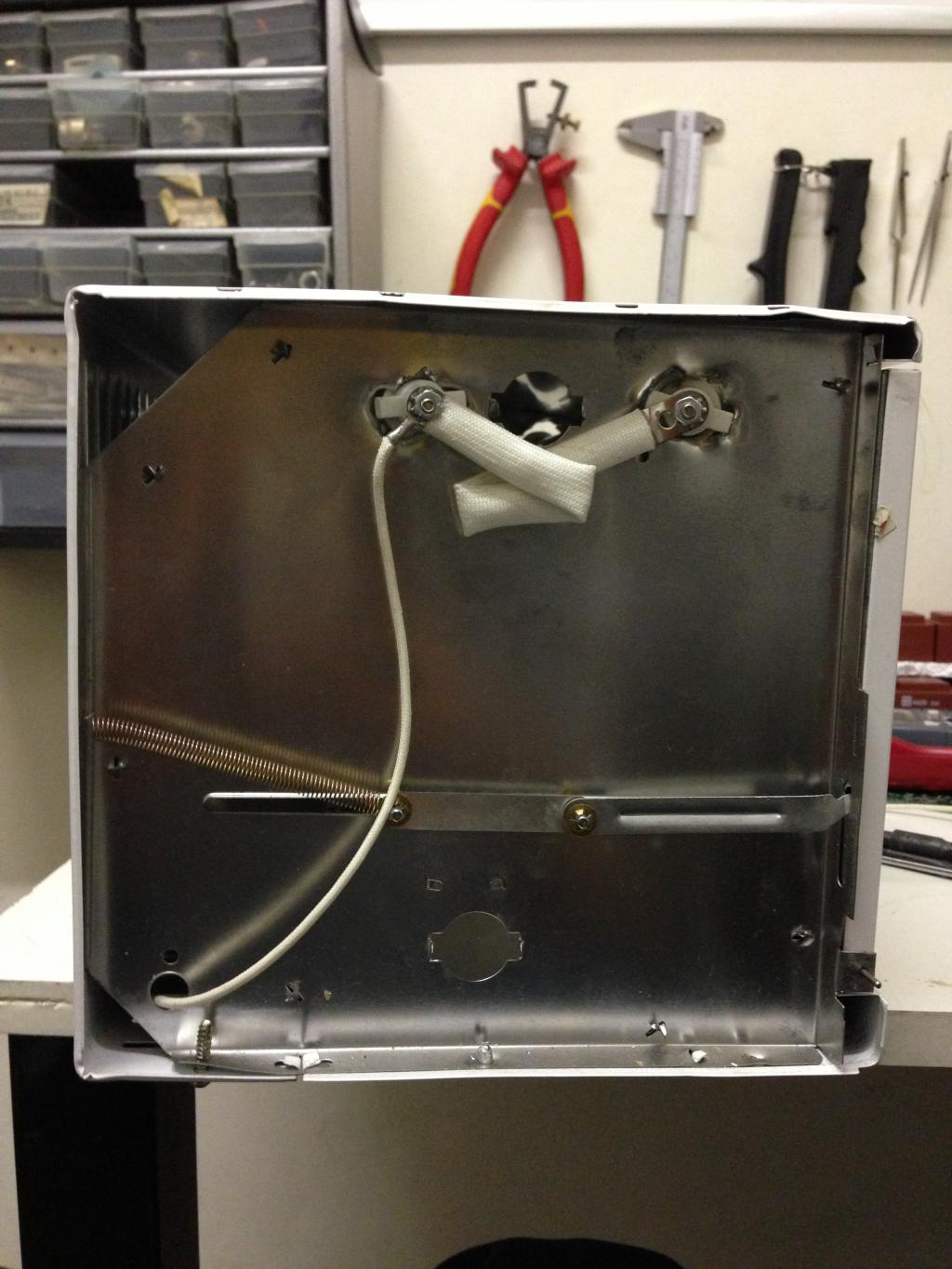
SO I am trying to build a small reflow oven controller, already have the oven ( a small 9liter model ) modified bringin both heating elements to the top , also a solid state relay to turn it on/off . ill figure pwm will have to do that later .
But for the moment I cant get to seem to get any temp readings out of the max 6675 ,
This is my second one , The first one , i think i blew it up by putting more then 5 volts acoss it by accident , but now the second ( these are not the cheapest ) is also not sowing me some love here
Anyone mind sharing a pice of code , I have tryied modifinig the one found in the obex(Mike Lord) that usualy works with a tv , but I need it to work on terminal to start with , after i got a 20X4 lcd already hooked and working . still no luck with it .
code used is below ,
CON
  _CLKMODE      = XTAL1 + PLL16X
  _XINFREQ      = 5_000_000

      SCK      =  0
      CS       =  1
      So       =  18

      TempScale  = 0     '1 is Farienheight   0 is Centegrade

    RS = 11      ' 1
    RW = 10      ' 2
    E  = 9      ' 3

    DBLow  = 12    ' 0
    DBHigh = 15

  ' ASCII codes.
    CR  = 13
    LF  = 10
    PSTClearScreen = 16

Var

       Long TempIn

OBJ

      Max6675       :  "Max6675_K_thermoCouple"
       pst : "parallax serial terminal"
        LCD : "LCD_20x4"


'====================================================================================
PUB _Start    |  TimeCnt_10Hz,  DisplayTime  , ElapsedCnt , index  , AddrVar
'====================================================================================


       Initialize

          LCD.RawSetPos( $00 ) ' "first" line
          LCD.RawWriteStr( string("reading sendor") )

        waitcnt(clkfreq *2 + cnt)

        repeat

             '  !Outa[LedPin]
               Max6675.ReadTemp(So, CS, SCK , TempScale , @TempIn  )

                pst.Str(String("Measured Temperture in Celsius = "))
                pst.dec( Tempin)
                pst.Str(String(" ",13))

              'LCD.RawSetPos( $40 ) ' "second" line
             ' LCD.RawWriteStr( string(Tempin) )

              waitcnt(clkfreq *2 + cnt)    'dont scan too fast or the conversion will not run


'====================================================================================
Pub  Initialize
'====================================================================================


   'Start cogs
           pst.start(115_200)
        waitcnt(clkfreq + cnt)
        pst.str(string(13,"MAX6675 ThermoCouple Demo.",13))

    LCD.usDelay( 5_0 ) ' time enough to switch to PST
     pst.str(string(13,"Start LCD Driver.",13))
    LCD.Init( E, RS, RW, DBHigh, DBLow )
    LCD.Clear
    LCD.usDelay( 2_000_000 )
{
''***************************************
''*  MAX675 v1.1                        *
''*  Author: Mike Lord                  *
''*  Copyright (c) Mike Lord            *
''*  Mike@electronicdesignservice.com   *
''*  650-219-6467                       *
''*  See end of file for terms of use.  *
''***************************************

' v1.0 - 01 Jul7 2011 - original version

This is written as a spin driver for the max6675 K type thermocouple chip.


┌─────────────────────────────────────┬────────────────┬─────────────────────┬───────────────┐
│ MAX6675 driver                      │ PG             | (C) 2011            | July 20 2011  |
├─────────────────────────────────────┴────────────────┴─────────────────────┴───────────────┤
│                                                                                            │
│ A driver for the MAX6675 K Type theromcouple chip                                          │
|                                                                                            |
| See end of file for terms of use                                                           |
└────────────────────────────────────────────────────────────────────────────────────────────┘
 SCHEMATIC
                      ┌────┐
             Gnd 1  │      │ 8 Nc
             T+  2  │MAX   │ 7 Sd
             T-  3  │6675  │ 6 Cs
             Vcc 4  │      │ 5 Sck
                      └──────┘


 }
CON


var   long stack1[20]
      long CogNr,InBit,Value


obj

      Tv        :  "Mirror_TV_Text"

'==================================================================
Pub  ReadTemp(SD, CS, SCK, TempScale , TempertureIn_Addr )  | Index  , AddrVar
'==================================================================
              ' SD, CS, SCK are the pin numbers of the propeller connected to the max6675
              'TempScale  = 1     '1 is Farienheight   0 is Centegrade

           dira[Cs] := 1
           dira[SCK] := 1
           dira[Sd] := 0


          Outa[Cs] := 1     'Make sure chip select is high


          Outa[SCK] := 0    'make sure Sck is low as initial value

          Outa[Cs] := 0     'Now take Chip select low to shart shift out of data

          'Tv.out($0A)      'X position follows
          'Tv.out( 1 + index )
          'Tv.out($0B)      'Y position follows
          'Tv.out( 3 )


          'Repeat Index from 0 to 15
                Waitcnt(clkfreq /10_000 + cnt)
                Outa[SCK] := 1
                Waitcnt(clkfreq /10_000 + cnt)
                Outa[SCK] := 0      'Data is now ready to be read

                Long[@TempertureIn_Addr] :=  67   'Ina[Sd]

                'Tv.hex( @TempertureIn_Addr, 4 )
               ' Tv.Str(String("-"))
                'Tv.dec(Long[@TempertureIn_Addr])
                'Tv.Str(String("  "))


     Outa[Cs]  := 1     'Make sure chip select is high
     Outa[SCK] := 0    'make sure Sck is low as initial value

           '  Tv.out($0D)
        'Tv.Str(String("after routine"))

  return

{

PUB SHIFTIN (Dpin, Cpin, Mode, Bits) : Value | InBit
{{
   Shift data in, master clock, for mode use BS2#MSBPRE, #MSBPOST, #LSBPRE, #LSBPOST
   Clock rate is ~16Kbps.  Use at 80MHz only is recommended.
     X := BS2.SHIFTIN(5,6,BS2#MSBPOST,8)
}}
    dira[Dpin]~                                            ' Set data pin to input
    outa[Cpin]:=0                                          ' Set clock low
    dira[Cpin]~~                                           ' Set clock pin to output

    If Mode == MSBPRE                                      ' Mode - MSB, before clock
       Value:=0
       REPEAT Bits                                         ' for number of bits
          InBit:= ina[Dpin]                                ' get bit value
          Value := (Value << 1) + InBit                    ' Add to  value shifted by position
          !outa[Cpin]                                      ' cycle clock
          !outa[Cpin]
          waitcnt(1000 + cnt)                              ' time delay

    elseif Mode == MSBPOST                                 ' Mode - MSB, after clock
       Value:=0
       REPEAT Bits                                         ' for number of bits
          !outa[Cpin]                                      ' cycle clock
          !outa[Cpin]
          InBit:= ina[Dpin]                                ' get bit value
          Value := (Value << 1) + InBit                    ' Add to  value shifted by position
          waitcnt(1000 + cnt)                              ' time delay

    elseif Mode == LSBPOST                                 ' Mode - LSB, after clock
       Value:=0
       REPEAT Bits                                         ' for number of bits
          !outa[Cpin]                                      ' cycle clock
          !outa[Cpin]
          InBit:= ina[Dpin]                                ' get bit value
          Value := (InBit << (bits-1)) + (Value >> 1)      ' Add to  value shifted by position
          waitcnt(1000 + cnt)                              ' time delay

    elseif Mode == LSBPRE                                  ' Mode - LSB, before clock
       Value:=0
       REPEAT Bits                                         ' for number of bits
          InBit:= ina[Dpin]                                ' get bit value
          Value := (Value >> 1) + (InBit << (bits-1))      ' Add to  value shifted by position
          !outa[Cpin]                                      ' cycle clock
          !outa[Cpin]
          waitcnt(1000 + cnt)                              ' time delay

    elseif Mode == OnClock
       Value:=0
       REPEAT Bits                                         ' for number of bits

          !outa[Cpin]                                      ' cycle clock
          waitcnt(500 + cnt)                               ' get bit value
          InBit:= ina[Dpin]                               ' time delay
          Value := (Value << 1) + InBit                    ' Add to  value shifted by position
          !outa[Cpin]
          waitcnt(500 + cnt)
Any help in the right direction would be greatly appriciated :P:thanks
Previeuw


Comments
I took a look at the OBEX listing. There are two drivers there. One is the suspect in-line object "MAX6675_K_ThermoCouple" as you have it above, and the other is "MAX6675_K_ThermoCouple_Cog", which runs in its own cog, and seems to be polished, and is is the one that should really read and return a value from the sensor.
the shifting in routine was never my strong point ,
@ JonnyMac , Thanks for the headsup with the code ,
Ive try implementing it , looks to be going in the good direction here , but dont understand it completly ,
The values comming out supose to be are not like the 0.25 range I suspect it to be
the return temp * 25 , i dont understand if its a 0.25 resolution based on 12 bits out of 16 bits , we suppose to shift to the right bits first(D-14-D3).
Going to need in in a value so I can make the rest of the calculations
OBJ

      Max6675       :  "Termomax6675.spin"            '"Max6675_K_thermoCouple"
       pst : "parallax serial terminal"
        LCD : "LCD_20x4"


'====================================================================================
PUB _Start    |  TimeCnt_10Hz,  DisplayTime  , ElapsedCnt , index  , AddrVar
'====================================================================================


       Initialize

          LCD.RawSetPos( $00 ) ' "first" line
          LCD.RawWriteStr( string("reading sendor") )

        waitcnt(clkfreq *2 + cnt)

        repeat

                TempReading := Max6675.tc
                pst.Str(String("Measured Temperture in Celsius = "))
                pst.dec (TempReading)
                pst.Str(String(" ",13))

              'LCD.RawSetPos( $40 ) ' "second" line
             ' LCD.RawWriteStr( string(Tempin) )

              waitcnt(clkfreq *2 + cnt)    'dont scan too fast or the conversion will not run


'====================================================================================
Pub  Initialize
'====================================================================================


   'Start cogs
           pst.start(115_200)
        waitcnt(clkfreq + cnt)
        pst.str(string(13,"MAX6675 ThermoCouple Demo.",13))

    LCD.usDelay( 5_0 ) ' time enough to switch to PST
     pst.str(string(13,"Start LCD Driver.",13))
    LCD.Init( E, RS, RW, DBHigh, DBLow )
    LCD.Clear
    LCD.usDelay( 2_000_000 )

    Max6675.start(CS, SCK, So)
[HTML]
MAX6675 ThermoCouple Demo.
Start LCD Driver.
Measured Temperture in Celsius = 5650
Measured Temperture in Celsius = 5600
Measured Temperture in Celsius = 5700
Measured Temperture in Celsius = 5600
Measured Temperture in Celsius = 5650
Measured Temperture in Celsius = 5700
Measured Temperture in Celsius = 5750
Measured Temperture in Celsius = 5750
Measured Temperture in Celsius = 5700
Measured Temperture in Celsius = 5650
Measured Temperture in Celsius = 5750
Measured Temperture in Celsius = 5650
Measured Temperture in Celsius = 5750
Measured Temperture in Celsius = 5600
Measured Temperture in Celsius = 5700
Measured Temperture in Celsius = 5750
Measured Temperture in Celsius = 5650
Measured Temperture in Celsius = 5750
Measured Temperture in Celsius = 5700
Measured Temperture in Celsius = 5600
Measured Temperture in Celsius = 5800
Measured Temperture in Celsius = 5750
Measured Temperture in Celsius = 5700
Measured Temperture in Celsius = 5750 [/HTML]
And I used JonnyMac code below (see OBJ Max6675 : "Termomax6675.spin" )
Bye the way , anyone know of a drop in 1 pin pwm to controll the solid state relay power% with a value
Many thanks again in advanve
If i change the reading part like below
temp := read
  if (hassensor == true)
    return temp
  else
    return -1
Wich give me a result that resembles the temperture in C more corretly , but im not sure im right about that , cause its supose to be a 0.25 resulution , and 225/4 = 56.C wich doesnt make sense for the room tempeture its in
[HTML]Measured Temperture in Celsius = 224
Measured Temperture in Celsius = 224
Measured Temperture in Celsius = 218
Measured Temperture in Celsius = 226
Measured Temperture in Celsius = 224
Measured Temperture in Celsius = 224
Measured Temperture in Celsius = 224
Measured Temperture in Celsius = 226
Measured Temperture in Celsius = 222
Measured Temperture in Celsius = 224
Measured Temperture in Celsius = 224
MMeasured Temperture in Celsius = 226
[/HTML]
I find 0.25C units inconvenient -- especially dealing with integer values. Multiplying by 25 is the same as multiplying by 0.25 and then by 100; the result is that we get 0.01 degree units; much easier to deal with and read in a display. You should see something like 2275 which would be 22.75 degrees C.
@WBA
I moved them both to the top to try to get a better heat spread on the pcb board , probably going to solder only on 1 side anyway , so think the one below is kinda useless to heat up the pcb from below if your not planning on double sided pcbś . I think I read it somewhere that it was better to move them both to the top , but cant recall where I read that , But seems to make some sens to mee , so I did it , When the temp reading and callibrating starts ill see if it does make sense or not . Ill post updates about it later
Havent seen a drop in easy to use Reflow Controller , based on the propeller , but I know allot must have done it cause it cant be easier with the Prop dropping in the right objects and building a top level controller for it , So im planning to release the code , schematic , and parts used to build it , so anybody can build it based on a propeller
Max6675+DS1820(just for ref) + 20*4 Char LCD + 10A SSR + plus a few buttons I think .
pri control_ssr(zcpin, ssrpin, p_level) | level         ' launch with cognew

'' Control SSR based on value (0 to 100) at address in p_level
'' -- zcpin is zero-cross input from AC
'' -- ssprin is control output to SSR

  dira[zcpin] := 0                                      ' force to input

  outa[ssrpin] := 1                                     ' start off
  dira[ssrpin] := 0

  repeat
    level := 0 #> long[p_level] <# 100                  ' keep in legal bounds
    if (level == 0)
      outa[ssrpin] := 0                                 ' off
    else
      outa[ssrpin] := 1                                 ' on
      repeat level
        waitpne(1 << zcpin, 1 << zcpin, 0)              ' wait for zero-cross
        waitpeq(1 << zcpin, 1 << zcpin, 0)

      outa[ssrpin] := 0                                 ' off
      repeat (100 - level)
        waitpne(1 << zcpin, 1 << zcpin, 0)
        waitpeq(1 << zcpin, 1 << zcpin, 0)
I've attached a schematic for zero-cross detection; this is tested -- I use it in an AC lighting controller. The 15K resistors at 2W each.
Here's an example of a commerical product I programmed and used this object in:
-- http://www.cameraturret.com/genesis.htm
True story: this controller was being used on a film shoot in some remote desert region and during a shot in a cave, a rock fell onto the device and broke the LCD. This could have been disastrous, but wasn't, because we had made such a simple interface with the UP, DN, LF, RT, ENT, and ESC buttons -- the operator was able to remember the button sequences and they got the shots they needed!
One of the useful methods in this object is called rjdec() for right-justified decimal values. This routine will get a lot of use displaying temperature and other values on your reflow controller.
About the LCD driver , Ill look into it , i know its indeed a thing always to get the value in the right format to get it display endso , I struggled with it allot also but I managed to get it working , going to look tru yours to see what more I can learn about it.
I did manage to get both the Max6675 and the DS1820 To display the reading on the LCD and in the Serial terminal , ( can comment out one of them if not used )
And overall I see I have a difference of about 7degrees between them , the max6675 reading the highest . but dont think thats going to be that big of a problem (add an offset i think ) also I am going to dived the readings by 100 still to get only hole degrees , cause that much precishon I probably cant controll anyway. so not needed and easyer i think to manage
Code used
CON
  _CLKMODE      = XTAL1 + PLL16X
  _XINFREQ      = 5_000_000

   DS1820_D_PIN = 17

    SCK      =  0  ' Max6675 Pin
    CS       =  1  ' Max6675 Pin
    So       =  18 ' Max6675 Pin

    TempScale  = 0     '1 is Farienheight   0 is Centegrade

    RS = 11        ' LCD Control Pins
    RW = 10        ' LCD Control Pins
    E  = 9         ' LCD Control Pins

    DBLow  = 12    ' LCD Data Pins
    DBHigh = 15    ' LCD Data Pins

  ' ASCII codes.
    CR  = 13
    LF  = 10
    PSTClearScreen = 16

    ' One Wire Values .
     CVRT_TEMP  = $44
     SKIP_ROM   = $CC
     RD_SPAD    = $BE

Var

       Long TempReading1, TempReading2

OBJ

      ow            : "jm_1-wire"
      Max6675       :  "jm_max6675.spin"            '"Max6675_K_thermoCouple"
      pst           : "parallax serial terminal"
      LCD           : "LCD_20x4"
      num           : "simple_numbers"
      f             : "Float32"
      fp            : "FloatString"


'====================================================================================
PUB _Start    |  TimeCnt_10Hz,  DisplayTime  , ElapsedCnt , index  , AddrVar
'====================================================================================


       Initialize

       LCD.RawSetPos( $40 ) ' "first" line
       LCD.RawWriteStr( string("Max6675:") )

       LCD.RawSetPos( $14 )                              {set lcd position}
       LCD.PrintStr( String("DS1820 :"))
        waitcnt(clkfreq *2 + cnt)

        repeat

              Get_Max6675_Reading
              Get_DS1820_Reading
              waitcnt(clkfreq  + cnt)    'dont scan too fast or the conversion will not run


'====================================================================================
Pub  Initialize | status
'====================================================================================

    'waitcnt(clkfreq*3 + cnt)                          'Give time to open terminal if not auto
    pst.start(115_200)                                 'Start Debug Serial Terminal
    pst.str(string(13,"Serial Terminal : Ready.",13))  'Lets us know the driver is working
    waitcnt(clkfreq + cnt)

    pst.str(string(13,"Start LCD Driver.",13))         'Start 20x4 Char LCD Driver
    LCD.Init( E, RS, RW, DBHigh, DBLow )
    LCD.Clear
    LCD.usDelay( 2_000_000 )
    LCD.RawSetPos( $00 ) ' "first" line
    LCD.RawWriteStr( string("LCD Started : Succes") )    'Lets us know the driver is working
    waitcnt(clkfreq *2+ cnt)
    LCD.Clear                                               'Clear Back the screen


    Max6675.start(CS, SCK, So)                              'Ini Max6675

    ow.init(DS1820_D_PIN)                                   'Ini DS1820 Temp Sensor  ( Used as reference )


'====================================================================================
PUB Get_Max6675_Reading
'====================================================================================

      TempReading1 := Max6675.tc01                              'Get reading from MAX6675

      pst.Str(String("Max6675 Temperture in Celsius = "))      'Display in terminal
      pst.dec (TempReading1)                                    'Display in terminal
      pst.Str(String(" ",13))                                   'Display in terminal

      LCD.RawSetPos( $48 )                                      'set lcd position
      LCD.PrintStr(num.dec(TempReading1))                       'Display on LCD


'====================================================================================
PUB Get_DS1820_Reading
'====================================================================================

      TempReading2 := readtc                                    'Get reading from DS1820 sensor

      pst.Str(String("DS1820 Temperture in Celsius = "))      'Display in terminal
      pst.dec (TempReading2)                                    'Display in terminal
      pst.Str(String(" ",13))                                   'Display in terminal

      LCD.RawSetPos( $1C )                                      'set lcd position
      LCD.PrintStr(num.dec(TempReading2))                       'Display on LCD


'====================================================================================
pub readtc | tc
'====================================================================================
'' Reads temperature from DS1820
'' -- returns degrees C in 0.1 degree units

  ow.reset
  ow.write(SKIP_ROM)
  ow.write(CVRT_TEMP)
  repeat                                                        ' let conversion finish
    tc := ow.rdbit
  until (tc == 1)
  ow.reset
  ow.write(SKIP_ROM)
  ow.write(RD_SPAD)
  tc := ow.read                                                 ' lsb of temp
  tc |= ow.read << 8                                            ' msb of temp
  ow.reset

  tc := ~~tc * 5                                                ' extend sign, 0.1° units

  return tc
Attached the complete Spin.zip folder so it can be a drop in , Just change the pins accordinglyMAX6675+DS1820_LCD_20*4.zip
So that part worked out pretty fine , reading the temp , think we can call the title of the post solved for that
Reflow still in the making
About the SSR . about now is the time that I start diging into how to run the oven at say 50%. I didnt dig into that yet ,
I did have a pice of code somewhere to pwm a led , so i was thinking of using modifing it somehow to get the relay at different power % controlled by a value , so I can controll it easly . .
Your explination of a triac working got me thinking again , ( I kinda avoided the triac always to understand it completly )
anyway , I do have experiance with a S202S02F Solid state relay
wich is a zero cross relay , and uses a smal ciruit (460ohm resistor + transistor and a diode ) to connect it to the propeller , But like the zerro crossing I had in mind I cant controll it that way , only controled it on/off before , wel that was wat i was thinking at least , propbablt wrong ,
Thats why i bought a Z240D10-17 - SSR, 10A that is direct switching , so I can toggle it directly , to controll it with say pwm , well that was my thinking , got to find that out still, the propeller does turn on /off , if i toggle the pin slowly, dont know about pwm yet. But your mentioning of AC and DC got me thinking again , Guess i will find out soon. Its just a wire that gets heated by pasing the power , I it was a different kind of divice i would be a bigger problem i think .
ill be working on it tonight and comming days to try to get this working , got some board im realy hopin that I can reflow in the future
The buttons design looks sweet , that means saving up pins to do other things , I bet that will com in handy many times in the future , Wil be testing that out i think . But I was thinking of using less buttons as possible , ( if is hady to work with only 2 buttons ) , probably going to use 1 reflow setting ( dont know how to call it , the time/temp that it needs to perform ) so I will program those hard in the program , and use the buttons to start /stop/ pause the program ,
Well lets just say , ill work with whatever works best
I rule!
Did you see that the updated version of my MAX6675 driver has a method called tc() that returns whole degrees? It rounds up based on the lower two bits.
With 50Hz line frequency you're going to have a 10ms (duration of AC half-cycle) granularity with your timing. What's working for you is the thermal inertia of the heating element. You might do something as simple as this -- crude, but with feedback should give you the control you want. As with the other code, this runs in its own cog.
pri ssr_control(ssrpin, p_level) | level ' launch with cognew outa[ssrpin] := 0 ' set to output dira[ssrpin] := 1 repeat level := 0 #> long[p_level] <# 100 ' get level, keep legal if (level > 0) outa[ssrpin] := 1 ' activate SSR waitcnt(cnt + (level * (clkfreq / 100))) ' hold for on timing if (level < 100) outa[ssrpin] := 0 ' de-activate SSR waitcnt(cnt + (100 - level) * (clkfreq / 100)) ' hold for off timingIn my experience "few buttons as possible" always means trickier code, and trickier product. While you don't have to implement the full 6-button interface I tend to use (there is even a patent in my name for a Toro irrigation controller that uses that interface), it does make things easier for the user. My object supports up to six buttons; you don't have to use them all (that is why there is a mask parameter).
That said, it's very easy to create a simple, little-or-no-training-required interface with six buttons. In my projects I use the LF and RT buttons to move between fields. I use UP and DN to change values in a field, ENTER to accept the new value, ESC to bail out without changing what was originally in the fields. Some years ago I coded a commercial HVAC controller using this code and it was a hit. Think about it; the cost of a few more buttons will not break the bank, and could save you hours of coding trying to do everything with just two buttons.
@Jonnymac , thanks again
I am pretty sure im going to implement the buttons interface , thats just to cool to not use , saving pins always good ,
just dont know it it will be with the reflow now, cause
I have a set of 4 buttons hardwired on the pcb already that I will be using , ( just so i dont have to go discover anything ) button = pin works fine , wont be needing the spare pins for now :P usualy use a monolicit lcd driven by 4 hc595 , so there I only use 3 pins but for 4 digits ,
thats why i have a different connection for the buttons on the pcb im using , I think those character lcd with the blue backlight like I have tend to give a product a chinees look , like aftermarket , thats why i prefeur the other ones while R&D for a new controller , Nothing wrong with it , just my thinking where I sell my controllers (dont take it personal , cause it aint
After been soldering allot latly I thouth now is the time to make that simple reflow controller to get the job speeded up , so ill be working to get it working , with just start stop tru terminal for now , just to get the reflowing job done :P
after that ill try to make it as user frendly as possible and building an interface with the buttons and a menu to set the variables needed , gotta find some time for that soon ,
and was hoping to get it working at least so I can use it to reflow a few pcb soon , (they are in production now )
Still need to get myself some stencils for the pcb to get the best result i think
But at the moment im finding out exactly around what temp the paste starts to evaporate , and how long I should keep it soaking there , and where the paste reflows and how long reflow gives the best result , ( the past datasheet only says 180c solder )
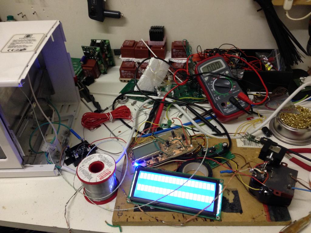
Was kinda bussy but manage to get it working , off course it still needs allot of tweaking but I managed to get some test runs with some old pcb that I have
done some runs with some tru hole components just to see what it does also , maybe that wil work :P hihhi
The pcb im plannin on are all smd so that has to be no problem , hopin to do 2 x 70*90mm boards at a time
Some pics
Code used
CON
  _CLKMODE      = XTAL1 + PLL16X
  _XINFREQ      = 5_000_000

    DS1820_D_PIN = 17

    SCK      =  0  ' Max6675 Pin
    CS       =  1  ' Max6675 Pin
    So       =  18 ' Max6675 Pin

    TempScale  = 0     '1 is Farienheight   0 is Centegrade

    RS = 11        ' LCD Control Pins
    RW = 10        ' LCD Control Pins
    E  = 9         ' LCD Control Pins

    DBLow  = 12    ' LCD Data Pins
    DBHigh = 15    ' LCD Data Pins

  ' ASCII codes.
    CR  = 13
    LF  = 10
    PSTClearScreen = 16

    ' One Wire Values .
     CVRT_TEMP  = $44
     SKIP_ROM   = $CC
     RD_SPAD    = $BE

     S_Temp = 1600    'Soak temperture to reach
     S_Time = 120     'Time in sec to soak at given temperture
     P_Temp = 1900    'Soak temperture to reach
     P_Time = 60      'Time in sec to soak at given temperture

Var

       Long TempReading1, TempReading2,tell,target,soaktime
       long numleds_, firstled_, persistence_, leds[7],Power
       long stack1[64]
       byte status_reflow
OBJ

      Max6675       :  "jm_max6675.spin"            '"Max6675_K_thermoCouple"
      pst           : "parallax serial terminal"
      LCD           : "LCD_20x4"
      num           : "simple_numbers"
      f             : "Float32"
      fp            : "FloatString"
      led           : "led_pwm"

'====================================================================================
PUB _Start    |  TimeCnt_10Hz,  DisplayTime  , ElapsedCnt , index  , AddrVar
'====================================================================================


       Initialize


         repeat  10    ' Loop in Idle  for 10 sec
          Home


       Ramp_to_Soak(S_Temp)       'Ramp to soaking temp given to variable

       Soak(S_Temp,S_Time)         'Soak for some time at give temp

       Ramp_to_Peak(P_Temp)        'Ramp to reflow temp given to variable

       Reflow(P_Temp,P_Temp)       'Reflow for some time at give temp

       Cooling                     'Shut off power to cool down back , all finished

  repeat
    Home                 'Just Loop in Idle

'====================================================================================
Pub  Home
'====================================================================================
      status_reflow := 0
      leds[0] := 0
      LCD.Clear
      Print_Status_Reflow                               'Show status of reflow
      Print_Max6675_Reading                             'Show current temp reading
      Print_Target_Temp
      Print_Power_Reflow
      waitcnt(clkfreq  + cnt)

'====================================================================================
Pub  Ramp_to_Soak(target_Temp)
'====================================================================================

 Tell:=0
 status_reflow := 1
 target := target_Temp
 power:= 50
  repeat

    if  TempReading1 < target_Temp
        Tell++
        leds[0] := 32
        LCD.Clear
        Print_Status_Reflow                               'Show status of reflow
        Print_Max6675_Reading                             'Show current temp reading
        Print_Target_Temp
        Print_Zone_Time
        Print_Power_Reflow
        waitcnt(clkfreq  + cnt)

    if  TempReading1 > target_Temp
        return

'====================================================================================
Pub  Soak(target_Temp,soak_time)
'====================================================================================

 soaktime := soak_time
 Tell:=0
 status_reflow := 2
 target := target_Temp

  repeat   soak_time

    if  TempReading1 < target_Temp
        power:= 5
        leds[0] := 1
        LCD.Clear
        Print_Status_Reflow                               'Show status of reflow
        Print_Max6675_Reading                             'Show current temp reading
        Print_Target_Temp
        Print_Zone_Time
        Print_Power_Reflow
        waitcnt(clkfreq  + cnt)

    if  TempReading1 > target_Temp
        power:= 0
        leds[0] := 0
        LCD.Clear
        Print_Status_Reflow                               'Show status of reflow
        Print_Max6675_Reading                             'Show current temp reading
        Print_Target_Temp
        Print_Zone_Time
        Print_Power_Reflow
        waitcnt(clkfreq  + cnt)

    Tell++

  return


'====================================================================================
Pub  Ramp_to_Peak(target_Temp)
'====================================================================================

 Tell:=0
 status_reflow := 3
 target := target_Temp
 power:= 100
  repeat

    if  TempReading1 < target_Temp
        Tell++
        leds[0] := 64
        LCD.Clear
        Print_Status_Reflow                               'Show status of reflow
        Print_Max6675_Reading                             'Show current temp reading
        Print_Target_Temp
        Print_Zone_Time
        Print_Power_Reflow
        waitcnt(clkfreq  + cnt)

    if  TempReading1 > target_Temp
        return


'====================================================================================
Pub  Reflow(target_Temp,soak_time)
'====================================================================================

 soaktime := soak_time
 Tell:=0
 status_reflow := 4
 target := target_Temp

  repeat   soak_time

    if  TempReading1 < target_Temp
        power:= 5
        leds[0] := 1
        LCD.Clear
        Print_Status_Reflow                               'Show status of reflow
        Print_Max6675_Reading                             'Show current temp reading
        Print_Target_Temp
        Print_Zone_Time
        Print_Power_Reflow
        waitcnt(clkfreq  + cnt)

    if  TempReading1 > target_Temp
        power:= 0
        leds[0] := 0
        LCD.Clear
        Print_Status_Reflow                               'Show status of reflow
        Print_Max6675_Reading                             'Show current temp reading
        Print_Target_Temp
        Print_Zone_Time
        Print_Power_Reflow
        waitcnt(clkfreq  + cnt)

    Tell++

  return


'====================================================================================
Pub  Cooling
'====================================================================================

      status_reflow := 5
      power:= 0
      leds[0] := 0
      LCD.Clear
      Print_Status_Reflow                               'Show status of reflow
      Print_Max6675_Reading                             'Show current temp reading
      Print_Zone_Time
      Print_Power_Reflow


  repeat

    if  TempReading1 > 3500
        Tell++
        leds[0] := 0
        LCD.Clear
        Print_Status_Reflow                               'Show status of reflow
        Print_Max6675_Reading                             'Show current temp reading
        Print_Zone_Time
        Print_Power_Reflow
        waitcnt(clkfreq  + cnt)

    if  TempReading1 < 3500
        status_reflow := 6
        return


'====================================================================================
Pub  Initialize | status
'====================================================================================

    LCD.Init( E, RS, RW, DBHigh, DBLow )                'Start The LCD driver in cog0
    LCD.Clear                                          'Clear Back the screen


     persistence_ := 0                             ' Converted a led pwm object to drive the relay ,
     numleds_ := 1                                 ' By far not the best solution but works :P
     firstled_ := 22                               ' Make sure to change the Fistled_ var to the SSR pin
     led.start(@numleds_)                          ' firstled_ := SSR pin

     cognew(Start_Max6675_Reading,@stack1)                'Start The Max6675 in a new cog

     Tell:=0

'====================================================================================
PUB Start_Max6675_Reading
'====================================================================================

     Max6675.start(CS, SCK, So)                              'Ini Max6675

   repeat


       TempReading1 := Max6675.tc01

       waitcnt(clkfreq + cnt)

'====================================================================================
PUB Print_Status_Reflow
'====================================================================================

    if status_reflow == 0
       LCD.RawSetPos( $00 )
       LCD.RawWriteStr( string("Status:") )

       LCD.RawSetPos( $07 )
       LCD.RawWriteStr( string("Idle") )

    if status_reflow == 1
       LCD.RawSetPos( $00 )
       LCD.RawWriteStr( string("Status:") )

       LCD.RawSetPos( $07 )
       LCD.RawWriteStr( string("Ramp to Soak") )


    if status_reflow == 2
       LCD.RawSetPos( $00 )
       LCD.RawWriteStr( string("Status:") )

       LCD.RawSetPos( $07 )
       LCD.RawWriteStr( string("Soaking ") )
       LCD.PrintStr(num.dec(soaktime))
       LCD.RawWriteStr( string("Sec") )

    if status_reflow == 3
       LCD.RawSetPos( $00 )
       LCD.RawWriteStr( string("Status:") )

       LCD.RawSetPos( $07 )
       LCD.RawWriteStr( string("Ramp 2 Peak") )

     if status_reflow == 4
       LCD.RawSetPos( $00 )
       LCD.RawWriteStr( string("Status:") )

       LCD.RawSetPos( $07 )
       LCD.RawWriteStr( string("Reflow") )

     if status_reflow == 5
       LCD.RawSetPos( $00 )
       LCD.RawWriteStr( string("Status:") )

       LCD.RawSetPos( $07 )
       LCD.RawWriteStr( string("Cooling") )

     if status_reflow == 6
       LCD.RawSetPos( $00 )
       LCD.RawWriteStr( string("Status:") )

       LCD.RawSetPos( $07 )
       LCD.RawWriteStr( string("Cooled") )

  return
'====================================================================================
PUB Print_Max6675_Reading
'====================================================================================
      LCD.RawSetPos( $40 )                                      ' set lcd position
      LCD.RawWriteStr( string("Actual:") )

      LCD.RawSetPos( $48 )                                      'set lcd position
      LCD.PrintStr(num.dec(TempReading1))                       'Display Temp on LCD

      LCD.RawSetPos( $4C )                                      ' set lcd position
      LCD.RawWriteStr( string("C") )

'====================================================================================
PUB Print_Target_Temp
'====================================================================================
      LCD.RawSetPos( $14 )                                      ' set lcd position
      LCD.RawWriteStr( string("Target:") )

      LCD.RawSetPos( $1C )                                      'set lcd position
      LCD.PrintStr(num.dec(target))                       'Display Temp on LCD

      LCD.RawSetPos( $20 )                                      ' set lcd position
      LCD.RawWriteStr( string("C") )


'====================================================================================
PUB Print_Zone_Time
'====================================================================================
      LCD.RawSetPos( $54 )                                      ' set lcd position
      LCD.RawWriteStr( string("Time:") )

      LCD.RawSetPos( $5A )                                      'set lcd position
      LCD.PrintStr(num.dec(Tell))                       'Display Temp on LCD

      LCD.RawSetPos( $60 )                                      ' set lcd position
      LCD.RawWriteStr( string("Sec") )

'====================================================================================
PUB Print_Power_Reflow
'====================================================================================
      LCD.RawSetPos( $60 )                                      ' set lcd position
      LCD.RawWriteStr( string("Pow:") )

      LCD.RawSetPos( $64 )                                      'set lcd position
      LCD.PrintStr(num.dec(Power))                       'Display Temp on LCD
      LCD.RawWriteStr( string("%") )

'====================================================================================
PUB Get_Power
'====================================================================================
      LCD.RawSetPos( $00 )                                      'set lcd position
      LCD.PrintStr(num.dec(leds))                               'Display on LCD
Zip of complete project filesReflow COntroller.zip
p.s. the temptc doesnt return a corrct value , but im using the hole numer reading anyway , but that could need some looking at :P . same for the SSR part . I used a led_pwm object modified , by no way the best solution , but it work , Ill do some more homework to make it better in future