

Propeller Simple Spin Board

Propeller Simple Spin Board
Propeller board minimal approach, assembles in 5 minutes, ideal beginner project
External Source
A simple design for a Propeller microntroller computer, the Propeller Simple Spin Board can be used to quickly write and test Spin programs.
ASSEMBLY
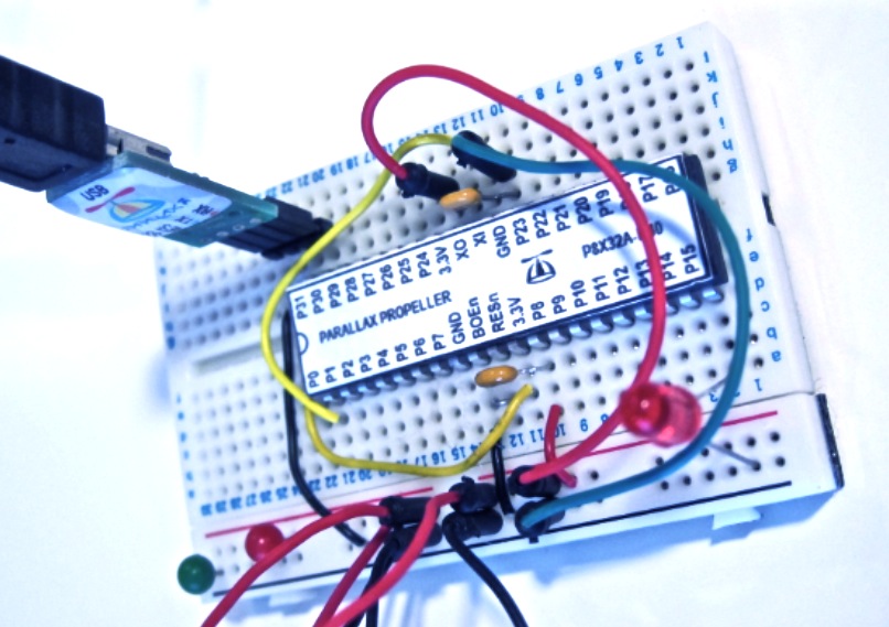
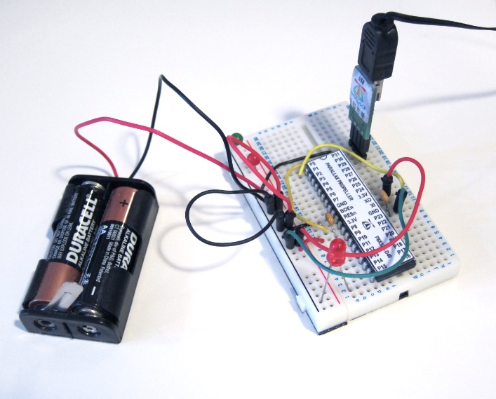
Assembles in 5 minutes using a solderless breadboard. This circuit is more simple than what's shown in the Parallax Propeller Education Kit. Parts include a Propeller chip and label, LED and hookup wire, two decoupling capacitors, and a couple AA batteries in a holder.
NO THIS AND NO THAT
The program is fed into the chip's RAM so no EEPROM is needed. The 5V LED runs on 3 volts and no dropping resistor is required. Software runs under RC Fast and RC enhancements so no crystal is needed. Batteries are used so no power supply components are needed.
THE BOARD
Stuff is mounted on one third of a Parallax breadboard from a Propeller Education Kit. Wiring is followed using the photo, no schematic needed.
EXTRAS
Extras include red and green colored stick pins for measuring at various points throughout the circuit. The simple battery holder has a lever action on/off switch.
MORE MINIMALISTIC
The circuit will run without the two capacitors. However, experts insist on using the decoupling components, so the caps are included in the circuit.
TEST PROGRAM
No project is complete without a test program. This simple Spin program will flash the LED on pin 15.
PARTS LIST
01 - Propeller Chip P8x32a-d40
01 - Propeller Chip Printed Label
01 - Parallax Prop Plug
01 - 4 Pin Connector
01 - 5V Red LED
02 - .1 uf Decoupling Capacitor
02 - Stick Pin (Red & Green)
01 - Set of Jumper Wires
01 - Battery Holder with Switch
02 - AA Battery
1/3 Breadboard

Simple Spin Board Wiring Image - the yellow wire near P1 is for experimenting only and not needed
PROPELLER PARTS FROM PARALLAX
http://www.parallax.com/PropellerEducationKit/tabid/377/Default.aspx
Propeller Simple Spin Board Schematic
Go to post 11 to find a new schematic or click below.
http://forums.parallax.com/attachment.php?attachmentid=102795&d=1373878746
Propeller board minimal approach, assembles in 5 minutes, ideal beginner project
External Source
A simple design for a Propeller microntroller computer, the Propeller Simple Spin Board can be used to quickly write and test Spin programs.
ASSEMBLY
Assembles in 5 minutes using a solderless breadboard. This circuit is more simple than what's shown in the Parallax Propeller Education Kit. Parts include a Propeller chip and label, LED and hookup wire, two decoupling capacitors, and a couple AA batteries in a holder.
NO THIS AND NO THAT
The program is fed into the chip's RAM so no EEPROM is needed. The 5V LED runs on 3 volts and no dropping resistor is required. Software runs under RC Fast and RC enhancements so no crystal is needed. Batteries are used so no power supply components are needed.
THE BOARD
Stuff is mounted on one third of a Parallax breadboard from a Propeller Education Kit. Wiring is followed using the photo, no schematic needed.
EXTRAS
Extras include red and green colored stick pins for measuring at various points throughout the circuit. The simple battery holder has a lever action on/off switch.
MORE MINIMALISTIC
The circuit will run without the two capacitors. However, experts insist on using the decoupling components, so the caps are included in the circuit.
TEST PROGRAM
No project is complete without a test program. This simple Spin program will flash the LED on pin 15.
pub main
dira[15] :=1
repeat
 outa[15] :=1
  waitcnt(clkfreq/2 + cnt)
  outa[15] := 0
  waitcnt(clkfreq/2 + cnt)
PARTS LIST
01 - Propeller Chip P8x32a-d40
01 - Propeller Chip Printed Label
01 - Parallax Prop Plug
01 - 4 Pin Connector
01 - 5V Red LED
02 - .1 uf Decoupling Capacitor
02 - Stick Pin (Red & Green)
01 - Set of Jumper Wires
01 - Battery Holder with Switch
02 - AA Battery
1/3 Breadboard
Simple Spin Board Wiring Image - the yellow wire near P1 is for experimenting only and not needed
PROPELLER PARTS FROM PARALLAX
http://www.parallax.com/PropellerEducationKit/tabid/377/Default.aspx
Propeller Simple Spin Board Schematic
Go to post 11 to find a new schematic or click below.
http://forums.parallax.com/attachment.php?attachmentid=102795&d=1373878746
806 x 569 - 125K
707 x 569 - 97K
Comments
-Tommy
M44D40+ and PowerTwig combo: Full Propeller circuit and 5v/3.3v supplies.
Here's a program with 5 statements instead of 7 to blink the LED on pin 15.
Disabling the Brownout Detector
In this first modification to the Propeller Simple Spin Board, the connection from BOEn to Ground is removed. Insert a new connection between BOEn and Vdd. This will disable the brownout detector by connecting it to high, and prevent the board from resetting at 2.7 volts or less.
The Propeller Simple Spin Board is capable of operations at voltages much lower than 3.3 or 2.7 volts and disabling the brownout detector BOEn will make this possible. This will allow longer battery operations as the voltage drops down. How low can you go below 2.7 volts? This is left as a student exercise.
The new schematic reflects this change. (soon to be posted)
For more information
http://tymkrs.tumblr.com/post/11655486643/propeller-non-general-purpose-pins-explained
Never mind, just looked more closely. Building a circuit off a pic is an exercise in itself!
Put an external pullup on RST. When BOE Brown Out Enable is grounded, the Propeller chip has an internal pullup activated. When BOE is held high, the internal pullup is not active, and an external pullup is required on RST to restore functioning.
I'm working on a schematic that reflects the fundamental circuit and will post it when finished. I often use pics instead of schematics, especially when working with breadboards where everything is visible from the top. The first pic was a general project overview and only the second pic was intended to show wiring more clearly. A schematic was posted here.
-Phil
Testing was with the LED blinking program. After installing this circuit, I noticed when the Prop Plug was still connected to the computer and the USB port was still active, a tiny amount of power was being fed into the circuit. It was enough to continue running the program in memory even when the 3.0 volt supply was cut off. Switching the 3 volts on again resulted in the LED blinking becoming brightly visible again. However, with the mains off, disconnecting the USB resulted in power and program loss.
Thanks for the advice on the BO disable. Smells a lot better in here. I left out the resistor for the LED (LED is expendable as well) in an effort to minimize any extra power drain.
RESULTS: I was able to lower the voltage to the point where the LED couldn't be seen 1.44 volts. I think I'll throw in a NPN and external power to see how low it really goes. I didn't realize a logic high/low could exist with such a small amount of voltage. Really cool experiment
There was some discussion on the forum a while back about powering the Prop with lower voltages.
Thanks! I missed that one. I'll check that next before bombarding this post with questions.
I had to use a transistor to keep the LED going. After that:
~1.18v blink slows down
~1.0v P15 constantly high, no RAM loss
~0.5v P15 goes Low, no RAM loss
<0.5v nothing and RAM loss
>1.67v required to flash RAM
*All voltages are approximate.
Great idea! One could simply run the PST Parallax Serial Terminal and a program to text "on...off...on...off... to emulate a blinking LED." The USB does not draw any power from the Propeller and this should allow lower power operations without the resistor or LED.
Retaining a Running Program
I tried this simple experiment today. The circuit was loaded with the blinking LED program. The USB cable and the Parallax Spin Tool were completely removed from the board. The board continued to blink the LED and run the program. With a small UPS, the board can retain an operational program in Propeller RAM memory for the life of the power source.
Does the USB connection interfere with the low power experiments?
Doesn't the Prop get some power from the Prop Plug?
It might not be a good idea to have a USB connection during low power experiments.
R1 should be a low value, probably not a good idea to omit for long term projects
R2 will need to changed based on the LED and power source, I used 1K 1/4w and 12v with a 2.3v LED @ 20ma (never did the math probably close enough for testing)
L1 is the LED
Q1 is a NPN, I used 2N2222
With a Prop Plug there probably isn't any power going into the circuit itself. I just tried re-doing it with the Prop Plug powered up and plugged in and achieved the same results. I think there are some boards that tap the USB power that don't use a Prop Plug.
I left USB unplugged because I thought it might make my USB unstable or corrupt my IDE somehow. I hope to test that out today too. This isn't something that anyone should be doing unless it is with spare parts they don't mind parting with
Yes, described in post #13.
Doing low power experiments require USB connection considerations or disconnect it.
This is very interesting. In my circuit, disconnecting the 3 volt power but keeping the USB line active keeps the program running. When the lights in the room were dimmed, I could see the LED continuing to blink, though it was dim. This may have something to do with the LED choice and that it was not connected to a resistor.
I've seen a lot of devices that tap into the USB port's 5-volt supply. I have a small desk fan that plugs into USB for power and two USB fans for the Big Brain.
This test has no stability problems with Mac BST and running the Propeller circuit with USB connected. After the time to install Mac BST, install the correct driver, and get the font installed properly, it has worked great.
with the Propeller Simple Spin Board
and "Non-crystalized Circuits"
One question and the point of forum discussions has regarded serial communications with the Propeller running in RC modes without a crystal. Because the Propeller Simple Spin Board has no crystal and runs in RCFAST mode, a debugging solution is needed.
The PST or Parallax Serial Terminal is a very good solution for PC endowed setups with "crystalized" Propeller circuits. In the case of the Propeller Simple Spin Board, we are using a Mac, BST, and no Propeller crystal. What is the solution to having a serial communications terminal up and running for input and output?
It's confirmed that working with a Mac BST, the BST's Terminal, and a Propeller chip in RCFAST mode, serial communications can be established. Here are the settings:
Propeller: no crystal, RCFAST default startup
Software: BST, BST Terminal, PST, Terminal LED.spin, Parallax Serial Terminal.spin
Settings: 1200 baud, 8-bits format, parity - none. The port is set to the Prop's port. Set Terminal Echo On to see the inputted values. Display ASCII.
Startup: Set up the Terminal first. Establish settings. (Baud, Format, Port) Then go to Communicate , set Terminal Echo, Display ASCII, and Connect. Now Compile and Load RAM. General send/receive/format PST statements are working to make this a viable solution. A zipped demo is attached along with the PST object, and a view of the working system. The provided demo program is the version that runs the terminal LED only.
I love your posts. While every irritant doesn't lead to the formation of a pearl, every time I invest my time in following one of your threads, I am never sorry:)
Many times, I learn something new, but even If I don't learn anything new, I at least get a nice warm feeling.
Now that this project is a wrap... might I suggest that your Big Brain needs the Prop2...
I'm wondering what the Big Brain will do with a new cortex... and improved eyes and ears.
Rich