

Need help with LED dimmer circuit
 christineee
Posts: 17
christineee
Posts: 17
I am trying to create a circuit that is able to adjust the brightness of the LED accordingly to different light level.
100% brightness: dark surrounding
70% brightness: dim surrounding
0%(off) brightness: lighted surrounding
So far i am only able to come out with a code that is able to turn on in dark surrounding and turn off in lighted surrounding.
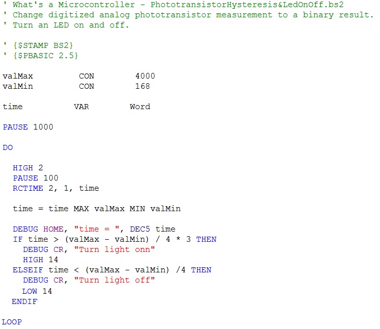
I found a set of coding(see below) and i need someone to explain what the meaning(highlighted in red)and how it helps the circuit to operate.
' BS2 PWM - Demonstrate BS2 "PWM" Function Operation
'
' This Program dims then brightens an LED.
'
' myke predko
'
' 05.09.11
'{$STAMP BS2}
'{$PBASIC 2.5}
' I/O Pins
LED PIN 14
' Variables
i VAR Word
' Mainline
DO
FOR i = 0 TO 254 ' Dim LED with PWM from
PWM LED, i, 5 ' 100% PWM to 0.4%
NEXT
DO WHILE (i <> 1) ' Brighten LED with PWM
PWM LED, i, 4
i = i - 1
LOOP
LOOP
Also, how can i modify it to suit my project?
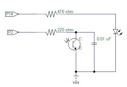
I have attach a copy of my schematic and code that i did.


Thanks in advance.
100% brightness: dark surrounding
70% brightness: dim surrounding
0%(off) brightness: lighted surrounding
So far i am only able to come out with a code that is able to turn on in dark surrounding and turn off in lighted surrounding.
I found a set of coding(see below) and i need someone to explain what the meaning(highlighted in red)and how it helps the circuit to operate.
' BS2 PWM - Demonstrate BS2 "PWM" Function Operation
'
' This Program dims then brightens an LED.
'
' myke predko
'
' 05.09.11
'{$STAMP BS2}
'{$PBASIC 2.5}
' I/O Pins
LED PIN 14
' Variables
i VAR Word
' Mainline
DO
FOR i = 0 TO 254 ' Dim LED with PWM from
PWM LED, i, 5 ' 100% PWM to 0.4%
NEXT
DO WHILE (i <> 1) ' Brighten LED with PWM
PWM LED, i, 4
i = i - 1
LOOP
LOOP
Also, how can i modify it to suit my project?
I have attach a copy of my schematic and code that i did.
Thanks in advance.
417 x 287 - 16K
746 x 645 - 85K
Comments
Do you still need help with this?
You might get better replies if you ask these type of questions in the Basic Stamp forum.
I haven't use a Basic Stamp for several years but I'll try to help a bit.
The "<>" symbol means not equal. The DO/LOOP will continue while "i" doesn't equal one.
There are several different ways of adjust the PWM value based on the brightness. You could use an equation which computes a PWM based on the brightness value. You could use a series of "IF", "ELSEIF" statements to set the PWM based on a range of brightness levels. You could use the "SELECT" and "CASE" statements instead of using multiple "IF", "ELSEIF" statements.
It's easier to read code posted to the forum if you use code tags. Here's a link to Phil's code tag tutorial.
So when it is in :
bright surrounding, both pin 14 and 13 will be low.
dim surrounding, pin 13 will be high and pin 14 will be low.
dark surrounding, both pin 14 and 13 will be high.
My new code is as follow:
' What's a Microcontroller - testing circuit 7.bs2
' Change digitized analog phototransistor measurement to a binary result.
' Turn an LED on and off.
' Switching LEDs to operate on different light level.


' {$STAMP BS2}
' {$PBASIC 2.5}


valMax         CON        4000                  'variable declaration
valMin         CON        168


time           VAR        Word


PAUSE 1000


DO


  GOSUB Rc_Time
  GOSUB Display


Rc_Time:                                        'to charge the capacitor.


  HIGH 2
  PAUSE 100
  RCTIME 2, 1, time


Display:


  time = time MAX valMax MIN valMin


  DEBUG HOME, "time = ", DEC5 time
  IF time > (valMax - valMin) / 4 * 3 THEN
    DEBUG CR, "Turn LED 100% on"                  'when time = more then 3/4 of the "turning led on" value.
    HIGH 14
    LOW 13
  ELSEIF time > (valMax - valMin) / 4 * 2 THEN
    DEBUG CR, "Turn LED 70% onn"                  'when time = more than 2/4 of the "turning led on" value.
    PWM 13, 190, 5000
    LOW 14
  ELSEIF time < (valMax - valMin) / 5 THEN
    DEBUG CR, "Turn LED 0% offf"                  'when time = less than 1/4 of the "turning led on" value.
    LOW 13
    LOW 14
  ENDIF


LOOP
However, now the problem i encounter is that the pin 13 when activated, it keeps flashing/flicker. Which part of my coding did i make a mistake? For the pin 14, there's no such problem.
Also, by adding that PWM command in my coding, does that make my led in pin 13 to light up to 75% brightness?
Thanks all in advance.
Below is the code whereby i change the PWM command to pin 13 HIGH.
Led in pin 13 does not flicker anymore. So i guess its the PWM command that has error?
How do i modify it then? Because so far i seen PWM command are to be written in this format: PWM led pin, duty cycle, duration
However, the led in pin 13 does not dim as i want it too.
' What's a Microcontroller - testing circuit 7.bs2 ' Change digitized analog phototransistor measurement to a binary result. ' Turn an LED on and off. ' Switching LEDs to operate on different light level. ' {$STAMP BS2} ' {$PBASIC 2.5} valMax CON 4000 'variable declaration valMin CON 168 time VAR Word PAUSE 1000 DO GOSUB Rc_Time GOSUB Display Rc_Time: 'to charge the capacitor. HIGH 2 PAUSE 100 RCTIME 2, 1, time Display: time = time MAX valMax MIN valMin DEBUG HOME, "time = ", DEC5 time IF time > (valMax - valMin) / 4 * 3 THEN DEBUG CR, "Turn LED 100% on" 'when time = more then 3/4 of the "turning led on" value. HIGH 14 LOW 13 ELSEIF time > (valMax - valMin) / 4 * 2 THEN DEBUG CR, "Turn LED 70% onn" 'when time = more than 2/4 of the "turning led on" value. HIGH 13 LOW 14 ELSEIF time < (valMax - valMin) / 4 THEN DEBUG CR, "Turn LED 0% offf" 'when time = less than 1/4 of the "turning led on" value. LOW 13 LOW 14 ENDIF LOOPThe PWM pin is inactive during the time that it takes to RCTIME and getting the IF..THEN..ELSE sorted out.
That's why there is flickering.
Additionally, I think the structure of your programme needs help.
I think that it ought to be:
DO GOSUB Rc_Time GOSUB Display LOOP Rc_Time: HIGH 2 PAUSE 100 RCTIME 2, 1, time RETURN Display: time = time MAX valMax MIN valMin DEBUG HOME, "time = ", DEC5 time IF time > (valMax - valMin) / 4 * 3 THEN DEBUG CR, "Turn LED 100% on" HIGH 14 LOW 13 ELSEIF time > (valMax - valMin) / 4 * 2 THEN DEBUG CR, "Turn LED 70% on" HIGH 13 LOW 14 ELSEIF time < (valMax - valMin) / 4 THEN DEBUG CR, "Turn LED 0% on" LOW 13 LOW 14 ENDIF RETURNI dont get you at this part. Do you mind explaining this to me in details.
I am not very good in understanding pbasic programming as this is my first time using it.
Thanks.
Remember that the DEBUG statement takes some time to execute and that will slow down your program. Each character sent by the DEBUG statement takes about 1ms to send. "Turn LED 0% on" takes 14 characters, thus a little over 14ms to execute. The other DEBUG statement (after the Display: label) takes another 13-14ms to execute. The Display: subroutine probably takes 35ms or so to execute
Thanks! Now i understand how it works.
So how do i make sure that the LED will not flicker? Should i move the PWM command up to the top/move it down the code? Or is there no way i can control the LED due to the time taken for the program to execute the other statements?
What to do?
There is a solution for your particular application that will allow you to keep the LED 'on' flicker free at a desired brightness. Keep in mind there are many ways to solve this, this is just a suggestion. By slightly modifying a basic LED current regulator circuit we can apply PWM to 'hold' the current at a particular value for short periods of time. Enough time that it allows the Basic Stamp II to process other things without flicker.
In the above image note that the input is inverted. This means that if you want the LED to turn 'on' you need to supply a LOW to the input of this circuit. Likewise for PWM ... A duty cycle of 255 will turn the LED 'off' while a duty cycle of 0 will turn it 'on' ... in practice the duty cycle ranged from 200 to 230 with 200 being full 'on' and 230 being full 'off'.
LED current regulator reference:
http://electronicdesign.com/energy/low-dropout-current-regulator-improves-led-driver-efficiency
In your original post you mentioned only 3 intensities, 100%, 70% and 0%. You don't need PWM for that. It can be done with two Stamp pins and two resistors. No flickering.
For example, here is a scheme.
...
If p13 is an input, and p14 is a low output, then call that 100% intensity. The LED is in series with 330Ω and the current is about 11.2mA. Then make pin p14 an input, and make p13 a low output. Now the LED is in series with 470Ω and the current is about 7.9 mA, which is ~70% of the first current. Make both pins high outputs (or both inputs) to get 0%. You get a bonus 170% current if you make both p13 and p14 low. Intensity may be a subjective thing, so you can adjust the resistor values to suit.
See, another way to solve the problem. Tracy Allen's approach is very simple, and all you might need to do is a little experimentation on which resistor values are best suited for your needs.
Thanks Tracy :-)
Thanks guys for teaching me.
Hi Tracy Allen,
May i know how do you get the value 11.2mA & 7.9mA?
Is it by applying the ohms law?
Cause these are the values i get..
V=IR ;
9V(power supply) ;
1.8V (voltage drop for RED LED)
100% brightness:
9V-1.8V=I*(330ohm)
I = 21.8mA
70% brightness:
21.8mA * 70% = 15.27mA
9V-1.8V=15.27mA*R
R = 471.51ohm ~ 470ohm
Thanks.