

MAX7219 Confusion
 xanatos
Posts: 1,120
xanatos
Posts: 1,120
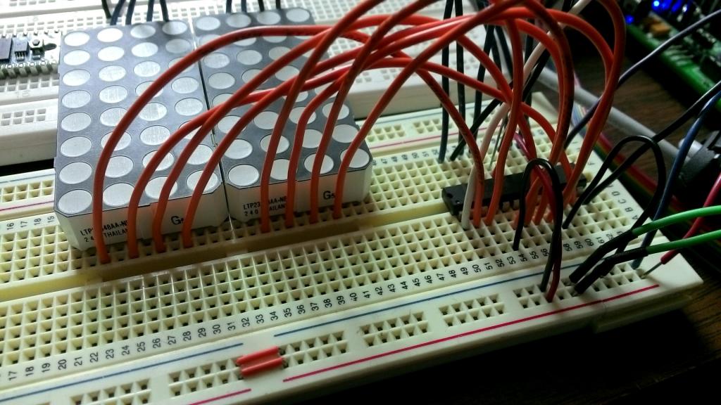
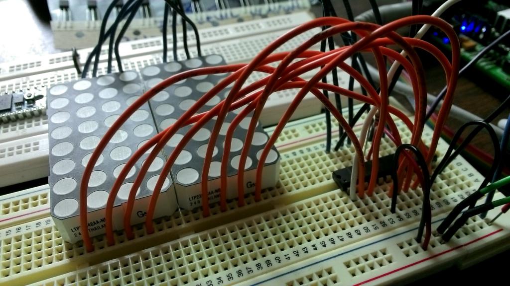
I'm using the MAX7219 with a pair of 4x8 matrix LEDs (see attached datasheet).
I have the MAX7219's "digits" lines connected to the cathodes of the matrix, and the "segments" lines connected to the anodes.
Here are the relevant code sections that I am starting with, taken from Chris Savage's "Binary Digital Clock" project:
There's a lot of other stuff in there so I'm just showing the useful sections.
I've tried changing the values for the registers for NoDecode from FF to 00 (I want individual segment control, not a character map output).
The display remains BLANK no matter what I put into the initialization routine.
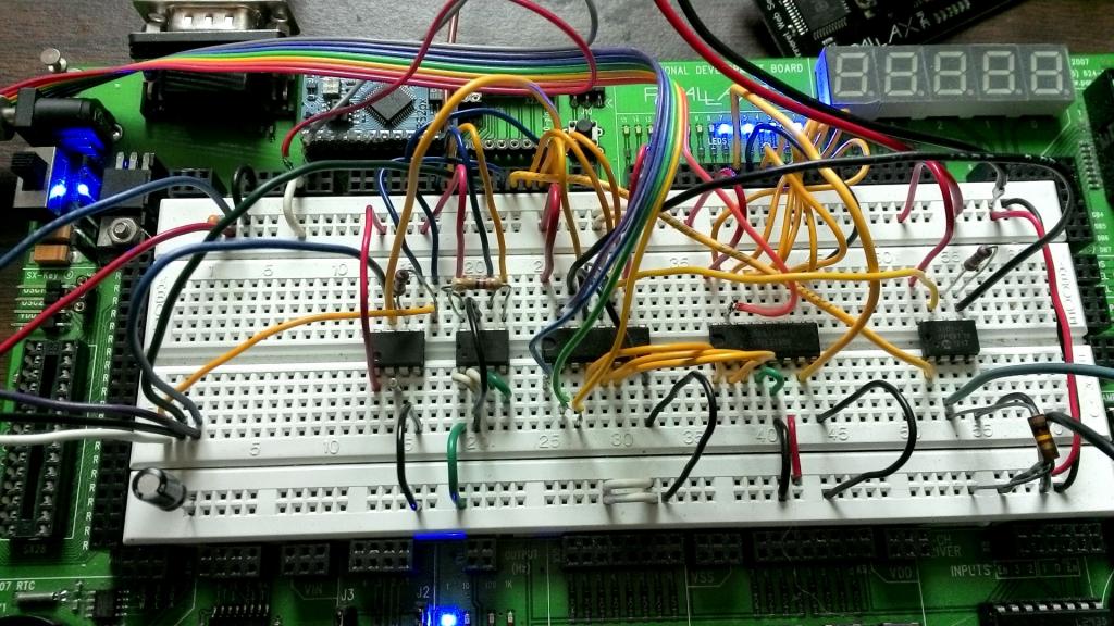
I'm uploading a few pictures of my wiring and the datasheet for the MAX7219. This looks like it should be simple enough - I just want to be able to light individual cells (these will indicate alarm conditions on any of my 100+ inputs) - but I am obviously doing something horribly wrong! :-) I'm thinking that once I have the setup data set correctly, I should then just be able to send my data to the 7219 in the form of the "digit" to select, and the "segments" for that digit that should be illuminated (which normally should be none... except when I'm trying to get it to light up by stuffing random test data in - but even that's not working!)
Please - help! :-)
Thanks,
Dave
I have the MAX7219's "digits" lines connected to the cathodes of the matrix, and the "segments" lines connected to the anodes.
Here are the relevant code sections that I am starting with, taken from Chris Savage's "Binary Digital Clock" project:
SClock          PIN     0                ' shift clock (74HC595.11, DS1302.7, MCP3202.7, MAX7219.13)
SDataIO         PIN     1                ' serial data (74HC595.14; DS1302.6 via 1k, MCP3202.6 [DO] via 1k, MCP3202.5 [DI], MAX7219.1)
M7219           PIN     5                ' MAX7219.12 CS for driving alarm panel LEDs


Decode          CON     $09              ' BCD Decode Register
Brite           CON     $0A              ' Intensity Register
Scan            CON     $0B              ' Scan Limit Register
ShutDn          CON     $0C              ' Shutdown Register (1 = On)
Test            CON     $0F              ' Display Test Mode
DecPnt          CON     %10000000        ' Decimal Point
Blank           CON     %1111            ' Blank A Digit

index           VAR     Byte             ' Loop Counter

d7219           VAR     Byte             ' Alarm Display
idxOdd          VAR     index.BIT0       ' Is Index Odd? (1 = Yes)


FOR index = 0 TO 7                      ' Initialize MAX7219
  LOOKUP index, [Scan, 7, Brite, 6, Decode, $00, ShutDn, 1], d7219
  SHIFTOUT SDataIO, SClock, MSBFIRST, [d7219]
  'IF (idxOdd = 0) THEN No_Load
  PULSOUT M7219, 5                    ' Latch The Data

No_Load:
NEXT

' -----[ Program Code ]----------------------------------------------------

Main:
    index = 1  ' This is incremented by another process
    d7219 = secs.LOWNIB                   ' Seconds (Ones Digit)
    d7219 = d7219 | DecPnt                ' Enable Decimal Point
    GOSUB AlarmPanelData
    index = index + 1                             ' Select Digit 1
    IF index > 7 THEN index = 0


' -----[ Subroutines ]---------------------------------------------------------------------------------------------------------

AlarmPanelData:
  SHIFTOUT SDataIO, SClock, MSBFIRST, [index, d7219]
  PULSOUT M7219, 5                    ' Latch Data
  RETURN
There's a lot of other stuff in there so I'm just showing the useful sections.
I've tried changing the values for the registers for NoDecode from FF to 00 (I want individual segment control, not a character map output).
The display remains BLANK no matter what I put into the initialization routine.
I'm uploading a few pictures of my wiring and the datasheet for the MAX7219. This looks like it should be simple enough - I just want to be able to light individual cells (these will indicate alarm conditions on any of my 100+ inputs) - but I am obviously doing something horribly wrong! :-) I'm thinking that once I have the setup data set correctly, I should then just be able to send my data to the 7219 in the form of the "digit" to select, and the "segments" for that digit that should be illuminated (which normally should be none... except when I'm trying to get it to light up by stuffing random test data in - but even that's not working!)
Please - help! :-)
Thanks,
Dave

1024 x 576 - 109K
1024 x 576 - 105K
1024 x 576 - 141K
Comments
Try Jon's code for None-Decode Mode,
' Listing 1' Nuts & Volts - February 2000 - Modified for (2) cascaded MAX7219 and (2) 8x8 LED Matrix Display ' -----[ Title ]----------------------------------------------------------- ' ' File...... LEDARRAY_MOD.BS2 ' Purpose... Uses the MAX7219 to drive a 8x8 LED array ' Author.... Jon Williams / Tim Gilmore ' E-mail.... jonwms@aol.com / gilmoret@us.saic.com ' Started... 06 JAN 2001 ' Updated... 18 APR 2007 ' {$STAMP BS2} ' -----[ Program Description ]--------------------------------------------- ' ' Demonstrates the use of Maxim's MAX7219 LED display driver in the ' non-decoded mode. In this mode, the programmer is responsible for ' sending segment (row) data for each digit (column). ' ' In this application, the MAX7219 is connected to a common-cathode LED ' array. The array is 8 columns wide by 8 rows tall (64 LEDs). The ' digit outputs from the MAX7219 are connect to the columns; the segment ' control lines to the rows. ' ' MAX7219 --> LED Connections: ' ' MAX7219.2 (0) --> Col 1 (left) ' MAX7219.11 (1) --> Col 2 ' MAX7219.6 (2) --> Col 3 ' MAX7219.7 (3) --> Col 4 ' MAX7219.3 (4) --> Col 5 ' ' MAX7219.17 (g) --> Row 1 (top) ' MAX7219.15 (f) --> Row 2 ' MAX7219.21 (e) --> Row 3 ' MAX7219.23 (d) --> Row 4 ' MAX7219.20 (c) --> Row 5 ' MAX7219.16 (b) --> Row 6 ' MAX7219.14 (a) --> Row 7 ' -----[ Revision History ]------------------------------------------------ ' ' 07 JAN 2001 - Version 1 ' 19 APR 2007 - Version 2 modified for (2) cascaded MAX7219 and (2) 8x8 LED Display Matrix ' -----[ I/O Definitions ]------------------------------------------------- ' Clock CON 0 ' shift clock to MAX7219 DPin CON 1 ' shift data to MAX7219 Load CON 2 ' ' -----[ Constants ]------------------------------------------------------- ' Decode CON $09 ' bcd decode Intensity CON $0A ' brightness Scan CON $0B ' scan (column) limit ShutDn CON $0C ' shutdown (1 = on) Test CON $0F ' display test mode NoOp CON $00 Yes CON 1 No CON 0 ' -----[ Variables ]------------------------------------------------------- ' index VAR Nib ' loop counter idxOdd VAR index.BIT0 ' is index odd? (1 = yes) d7219 VAR Byte ' data for MAX7219 d7219A VAR Byte char VAR Byte ' character ee address col VAR Nib ' column value row VAR Nib ' row value eeAddr1 VAR Byte ' ee pointer eeAddr1A VAR Byte eeAddr2 VAR Byte eeAddr2A VAR Byte vScroll VAR Word ' scrolling data buffer vScrollA VAR Word ' -----[ EEPROM Data ]----------------------------------------------------- ' Space DATA 000000 DATA 000000 DATA 000000 DATA 000000 DATA 000000 DATA 000000 DATA 000000 DATA 000000 DATA 0 UC_Ltr_P DATA 000000 DATA 000000 DATA 111111 'P DATA 001001 DATA 001001 DATA 001001 DATA 000110 DATA 000000 DATA 0 LC_Ltr_A DATA 000000 DATA 100000 'a DATA 010100 DATA 010100 DATA 010100 DATA 111000 DATA 000000 DATA 0 LC_Ltr_R DATA 000000 DATA 000000 DATA 111100 'r DATA 001000 DATA 000100 DATA 001000 DATA 000000 DATA 000000 DATA 0 LC_Ltr_A2 DATA 000000 DATA 100000 'a DATA 010100 DATA 010100 DATA 010100 DATA 111000 DATA 000000 DATA 0 LC_Ltr_L DATA 000000 DATA 000000 DATA 000000 'l DATA 000001 DATA 111111 DATA 000000 DATA 000000 DATA 00000 DATA 0 LC_Ltr_L2 DATA 000000 DATA 000000 DATA 000000 'l DATA 000001 DATA 111111 DATA 000000 DATA 000000 DATA 00000 DATA 0 LC_Ltr_A3 DATA 000000 DATA 100000 'a DATA 010100 DATA 010100 DATA 010100 DATA 111000 DATA 000000 DATA 0 LC_Ltr_X DATA 000000 DATA 000000 DATA 000100 'x DATA 101000 DATA 010000 DATA 101000 DATA 000100 DATA 000000 DATA 0 Char_Space DATA 000000 DATA 000000 DATA 000000 DATA 000000 DATA 000000 DATA 000000 DATA 000000 DATA 000000 DATA 0 ' column between characters Char_B DATA 000000 DATA 000000 DATA 111111 ' xxxxxxx DATA 001001 ' x..x..x DATA 001001 ' x..x..x DATA 001001 ' x..x..x DATA 110110 ' .xx.xx. DATA 000000 DATA 0 Char_S DATA 000000 DATA 100110 ' .x..xx. DATA 001001 ' x..x..x DATA 001001 ' x..x..x DATA 001001 ' x..x..x DATA 110010 ' .xx..x. DATA 000000 DATA 000000 DATA 0 Char_2 DATA 000000 DATA 000010 ' x....x. DATA 100001 ' xx....x DATA 010001 ' x.x...x DATA 001001 ' x..x..x DATA 000110 ' x...xx. DATA 000000 DATA 000000 Pad DATA 0,0,0,0,0,0,0,0 DATA 0 Char_Space2 DATA 000000 DATA 000000 DATA 000000 DATA 000000 DATA 000000 DATA 000000 DATA 000000 DATA 000000 DATA 0 ' column between characters ' -----[ Initialization ]-------------------------------------------------- ' Initialize: DIRL = 1 ' clock, data and load pins SHIFTOUT Dpin,Clock,MSBFIRST,[Scan,7,Scan,7] PULSOUT Load,3 SHIFTOUT Dpin,Clock,MSBFIRST,[Intensity,7,Intensity,7] PULSOUT Load,3 SHIFTOUT Dpin,Clock,MSBFIRST,[ShutDn,1,ShutDn,1] PULSOUT Load,3 ' -----[ Main Code ]------------------------------------------------------- ' Main: Flash_Characters: ' on screen, one at a time FOR char = 0 TO 9 LOOKUP char,[Char_B,Char_S,Char_2,Char_Space],eeAddr1 LOOKUP char,[UC_Ltr_P,LC_Ltr_A,LC_Ltr_R,LC_Ltr_A2,LC_Ltr_l,LC_Ltr_l2,LC_Ltr_A3, LC_Ltr_x,Char_Space],eeAddr1A GOSUB ShowChar PAUSE 1000 NEXT Crawl_Characters: ' crawl on (horizontally) FOR eeAddr1 = Space TO Char_Space2 GOSUB ShowChar2 NEXT PAUSE 1000 Scroll_Characters: ' scroll on (vertically) FOR char = 0 TO 8 LOOKUP char,[Char_Space,Char_B,Char_S,Char_2,Char_Space,Char_Space,Char_Space,Char_Space,Char_Space],eeAddr1 LOOKUP char,[Char_B,Char_S,Char_2,Char_Space],eeAddr2 LOOKUP char,[Char_Space,UC_Ltr_P,LC_Ltr_A,LC_Ltr_R,LC_Ltr_A2,LC_Ltr_l,LC_Ltr_l2,LC_Ltr_A3, LC_Ltr_x],eeAddr1A LOOKUP char,[UC_Ltr_P,LC_Ltr_A,LC_Ltr_R,LC_Ltr_A2,LC_Ltr_l,LC_Ltr_l2,LC_Ltr_A3, LC_Ltr_x,Char_Space],eeAddr2A FOR row = 1 TO 8 FOR col = 1 TO 8 READ (eeAddr1 + col - 1),vScroll.LOWBYTE READ (eeAddr2 + col - 1),vScroll.HIGHBYTE READ (eeAddr1A + col - 1),vScrollA.LOWBYTE READ (eeAddr2A + col - 1),vScrollA.HIGHBYTE d7219 = vScroll >> (row - 1) ' get "frame" d7219A = vScrollA >> (row - 1) ' get "frame" SHIFTOUT Dpin,Clock,MSBFIRST,[col,d7219A,col,d7219] PULSOUT Load,3 NEXT PAUSE 100 NEXT NEXT PAUSE 1000 GOTO Main END ' -----[ Subroutines ]----------------------------------------------------- ' ShowChar: FOR col = 1 TO 8 ' character is 8 columns wide READ (eeAddr1 + col - 1),d7219 ' read column data from EEPROM READ (eeAddr1A + col - 1),d7219A SHIFTOUT Dpin,Clock,MSBFIRST,[col,d7219A,col,d7219] PULSOUT Load,3 NEXT RETURN ShowChar2: FOR col = 1 TO 8 ' character is 8 columns wide READ (eeAddr1 + col - 1),d7219 ' read column data from EEPROM SHIFTOUT Dpin,Clock,MSBFIRST,[col,0,col,d7219] PULSOUT Load,3 NEXT FOR col = 1 TO 8 ' character is 8 columns wide READ (eeAddr1 + col - 9),d7219 ' read column data from EEPROM SHIFTOUT Dpin,Clock,MSBFIRST,[col,d7219,col,0] PULSOUT Load,3 NEXT RETURNTHANKS GUYS!
Dave