MCP23017 and INT question
Hello folks,
I have a question. I am designing a board using multiple MCP23017's, and I want to make sure that what I am doing with the interrupt pins is ok. I'd like to be able to use the interrupt signal from the chip, even though in my application, I will just have a cog polling dedicated to scanning the inputs. Since my application is slow (reading switches), I should be ok, and not miss any button presses.
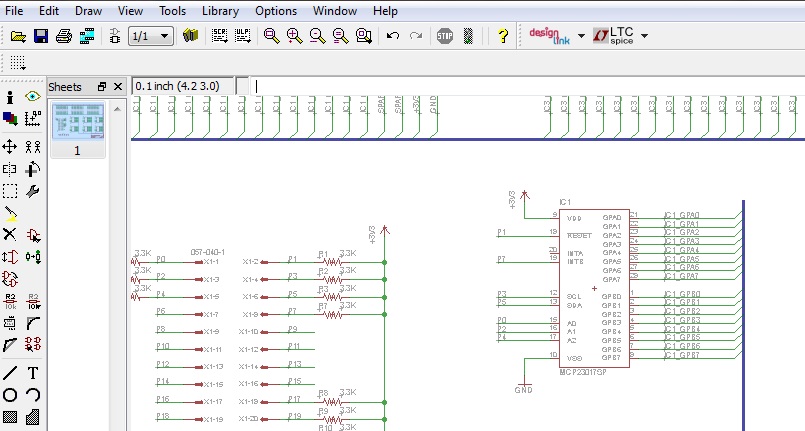
I have attached a screen shot of my circuit I am using. I have a pull-up resistor off the interrupt signal, and I am using INTB. I would like to use interrupt mirroring so that either INTA or INTB shows up on INTB pin.
I am using John McPhalen's MCP23017 object, but noted that there isn't a "configure interrupt", so if I added this:
and used this in my program: (mcp is the object name)
What number would I need to use to turn on port mirroring?
I'm going to use dec110 (bin01101110) for the ICON number this sets mirroring on, and sets the output to open drain.
Would this work for what I want to do? I'm going to test this tonight, but want to check before I get off. Can I just use either INT pin?
Another question: For multiple MCP23017's, do I start the first MCP, read the inputs, stop that MCP, start the next MCP, read the inputs, stop that MCP, etc Would I need to set IOCON each time as well as the other CFG parameters? Will that hurt anything or is there a better way?
Thanks in advance..
I have a question. I am designing a board using multiple MCP23017's, and I want to make sure that what I am doing with the interrupt pins is ok. I'd like to be able to use the interrupt signal from the chip, even though in my application, I will just have a cog polling dedicated to scanning the inputs. Since my application is slow (reading switches), I should be ok, and not miss any button presses.
I have attached a screen shot of my circuit I am using. I have a pull-up resistor off the interrupt signal, and I am using INTB. I would like to use interrupt mirroring so that either INTA or INTB shows up on INTB pin.
I am using John McPhalen's MCP23017 object, but noted that there isn't a "configure interrupt", so if I added this:
pub wr_cfgint(outbits)

'' Write value to interrupt cfg register

  i2c.start
  i2c.write(slaveid)
  i2c.write(IOCON)
  i2c.write(outbits)
  i2c.stop
and used this in my program: (mcp is the object name)
mcp.wr_cfgint(110)
What number would I need to use to turn on port mirroring?
I'm going to use dec110 (bin01101110) for the ICON number this sets mirroring on, and sets the output to open drain.
Would this work for what I want to do? I'm going to test this tonight, but want to check before I get off. Can I just use either INT pin?
Another question: For multiple MCP23017's, do I start the first MCP, read the inputs, stop that MCP, start the next MCP, read the inputs, stop that MCP, etc Would I need to set IOCON each time as well as the other CFG parameters? Will that hurt anything or is there a better way?
Thanks in advance..


Comments
In my reading of the docs -- page 18 -- you would set the IOCON register to %0100_0100. Setting BIT2 enables active-drain output (make sure you have a pull-up on the INT pin you're using) and setting BIT6 enabled interrupt mirroring. Should be pretty easy. By using open-drain outputs you can tie all INT lines together to a single input on your Propeller.
I'm assuming you're using I2C. There is no "turning on" or "turning off" the devices; you simply poll the device you want access to -- this is based on the A2..A0 pins (these need to be different for each device). You will need to configure each device's IOCON register; do this in your initial setup. After that you can check your INT pin input and if it's changed poll your devices.
Note that the design of my object means you'll define an object for each chip. For example, in a project I did a few years ago I had two sets of eXternal IO so I defined the objects like this:
obj

  xio0 : "jm_mcp23017"
  xio1 : "jm_mcp23017"
I admit these are not wildly original object names; in the program there were more cleverly named methods that made program use easy.
Why make your program more difficult to review and read by others by using decimal values? The Spin compiler is very happy to use binary values. I see this a lot -- and it leads to a lot of bugs in code. Honestly, it's faster and easier to enter a binary value in the editor than to convert to decimal.
As to the control word, I had the other bits on since they also seemed reasonable. I'll go with your suggestion though and see how that does. Your suggestion makes sense also, since that would imply the default setting is %0000_0000.
Thanks also about bringing up the obj. I bounce around so many different architectures I forgot about that. I'm wearing my PLC brain this week.