need help understanding I2C
As some of you know i have been working on my "Autonomous Tri-copter project"
It uses the MPU-9150 chip (Documentation: http://www.invensense.com/mems/gyro/documents/PS-MPU-9150A.pdf and Registry map: http://www.invensense.com/mems/gyro/documents/RM-MPU-9150A-00.pdf )
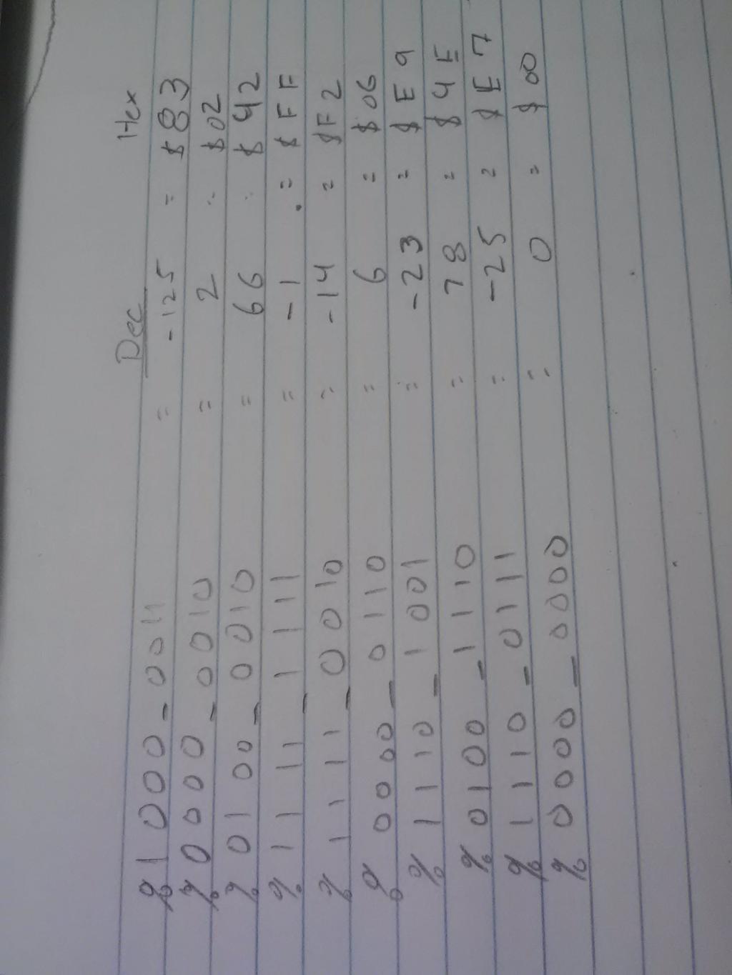
I have gotten "some" data back ( I attached a picture of what i had received written down, along with my code)
I used the I2c driver.spin and i tried the Basic i2c driver.spin.
So i guess what I don't understand is registry maps and how to use them, what I'm looking for in the code that i get back, and how come in the example code that i have seen there is no waiting for ACK before sending the next command?


Comments
I don't have a driver for the 9150 yet, but if you compare the ITG3200 driver I wrote with the datasheet for it, it might help a bit. The routines in there for setting / reading registers should work with almost no modification. The configuration code and code to read the sensor values will need to change for the appropriate register addresses and settings, but it may be easier than starting from scratch.
The attached file is a Spin version that should be a bit easier to follow, and does the initial register setting for the ITG, then reads the sensor values for temperature, x, y, and z. It uses single writes for the configuration, but sequential (auto-incrementing) reads for the sensor registers.
The ITGWriteRegisterByte function writes a value to a specific register on the chip, so ITGWriteRegisterByte( 22, $1A ) would set register 22 to the value 26 ($1A).
The ITGStartRead function sets up a sequential read operation from a specified address. The ContinueRead function reads a single byte from that address, and tells the chip to auto-increment to the next register. The FinishRead function reads a byte a signals that the read is complete.
Make sure that the chip ID value you're sending is a 7-bit value PLUS an additional 8th bit - the last bit tells the chip you're either reading or writing.
In my code it looks like this:
PRI  ITGReadRegisterByte( addr ) : result
    StartSend
    WriteByte( %11010010 )     ' 7 bits, plus a zero bit, total of 8 bits - this is a write
    WriteByte( addr )          ' The address of the register to read from
    StartSend
    WriteByte( %11010011 )     ' 7 bits, plus a one bit, total of 8 bits - this is a read
    result := ReadByte( 1 )
    StopSend
So, the address the datasheet tells you is usually the 7-bit version. Your code will need to shift it up by one bit, and concatenate the 0/1 bit to it, or you can hard wire it like I've done in the above code. Getting the ID wrong was the thing I did most often the first few times I wrote drivers. The chips often have a pin that allows you to select from two different IDs. The 9150 breakout from Sparkfun provides the pullup resistors, so you won't have to deal with those.
It might be that the example code isn't written to deal with ACKs. Of course ACKs (or NACKs) happen almost immediately after every 8 bits of data are transferred. Whether it's the master sending ACK to the slave to notify that more data is requested, or the slave sending ACK to the master notifying that it received the address. I don't know if this helps or not...
Delays in the reception of data are done by "clock stretching" where the slave keeps a clock pulse low (normally provided by the master) until the data bit is actually placed on the bus. Read the description of the I2C bus protocol on the Wikipedia for details.
http://www.nxp.com/documents/user_manual/UM10204.pdf
This is the official description of the I2C interface - the proverbial "horses mouth".
@Jason I messed /w the sample for a while and got nothing. I don't exactly understand what registers NEED to be written to to begin reading the sensor registers...
In the code attached i attempted to write to initialize the self_test, then read the other self_test registers. (Obviously it didn't work but...)
EDIT: There is a chance i had the correct code at one point because i had saved MPU-9150. spin in the prop library( the one my "code" was using, And another MPU-9150. spin on my desktop. (The one i was editing but not using)
I'll keep trying!!
Hey thanks - that is really interesting reading. I didn't realise there were so many fast modes, up to megabits per second. This has got me thinking about two propeller chips, master and slave, talking via the ultra-fast 5Mhz I2C protocol...