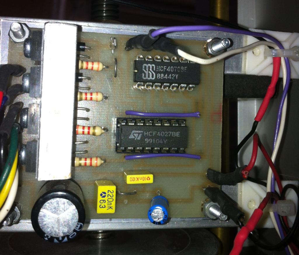
Odd stepper motor control circuit
Hello all,
So I'm working on updating an apparatus for bees. (Bees can learn!) It is an apparatus built by some other colleges, and the software is giving my lab a lot of trouble. I am going to switch control of the apparatus from a PC with troublesome software to a Propeller. I'll add some easy to disconnect cables to the control lines so we can swap the apparatus back to PC control if ever needed.
Some bits of circuitry are weird, but I think it is because of the serial connection the software uses. For example, three inputs (2 microswitches, 1 IR beam) are read by a CD40105BE storage register. I may or may not bypass that for the inputs.
What is really interesting to me is the circuit that controls the stepper motor. (See attached image. From PC - blue and white cables. Power and ground - red and black cables.) The motor is an old Howard 1-19-3403. I haven't completely traced the circuit, because it is not easy to see without disassembling the apparatus completely. But it looks like the serial line controls an HCF4070BE Quad Or Gate, which then controls a HCF4027BE J-K Flip Flop (or maybe the serial line controls both). Somehow, these control the four transistors that activate the stepper motor (whole steps). It just seems bizarre to me. Why not just activate the transistors directly?
Okay, so now the question part of the post. Has anybody seen a step motor controlled this way? Does it make sense to try to figure out this circuit, or should I just build something else to bypass it? (I'm leaning toward bypassing. Time is more important than money right now.)
Any thoughts would be appreciated, and I'll keep the thread updated with my progress.


Comments
Reference Schematic: "The Robot Builder's Bonanza", by Gordan McComb
http://www.aaroncake.net/circuits/stepper.asp
BTW) Gordon happens to be one of our forum members that will poke his head in from time to time.