Parallax GPS module help
Hello,
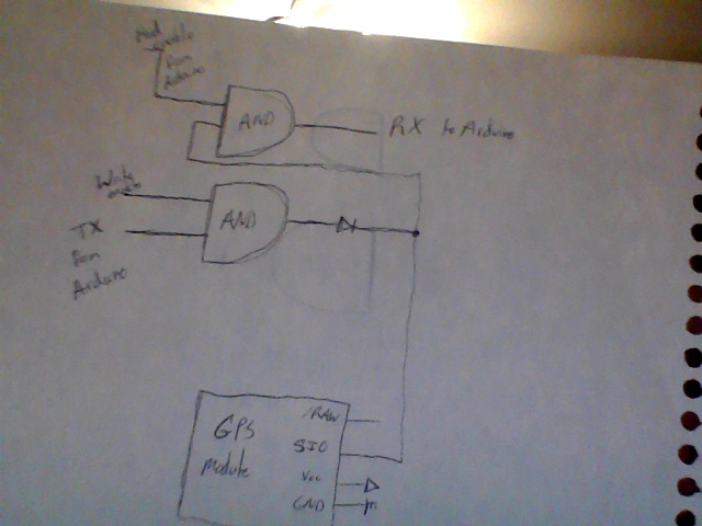
So, I am currently trying to interface an arduino with a Parallax GPS module. This module only has one serial communication line, whereas the arduino needs two. The module also has a Smart Mode so that when a command signal is sent, a specific byte(s) is sent back. To overcome the one line problem, I am using an AND gate to enable reading and writing only when I want to read or write.
What I'm doing with this makes complete sense in my head, but for some reason the GPS module only responds with 0's. The AND gate is fast enough to be used in this scenario; I've tested it with only reading.
Here is the data sheet for the GPS module: http://www.parallax.com/dl/docs/prod/acc/gpsreceivermanual1.0.pdf
Here is my code:
Below is a schematic:

So, I am currently trying to interface an arduino with a Parallax GPS module. This module only has one serial communication line, whereas the arduino needs two. The module also has a Smart Mode so that when a command signal is sent, a specific byte(s) is sent back. To overcome the one line problem, I am using an AND gate to enable reading and writing only when I want to read or write.
What I'm doing with this makes complete sense in my head, but for some reason the GPS module only responds with 0's. The AND gate is fast enough to be used in this scenario; I've tested it with only reading.
Here is the data sheet for the GPS module: http://www.parallax.com/dl/docs/prod/acc/gpsreceivermanual1.0.pdf
Here is my code:
#include <SoftwareSerial.h>


SoftwareSerial mySerial(10, 11); // RX, TX


// AND gates are fast enough for 4800 baud rate!


int readPin = 2;
int writePin = 3;


int incomingByte;
int message;


byte zero = 0x00;
byte one = 0x01;
byte two = 0x02;
byte nine = 0x09;


void setup()  {

  pinMode(readPin, OUTPUT);
  pinMode(writePin, OUTPUT);

  Serial.begin(9600);

  mySerial.begin(4800);
}


void loop()  {

    digitalWrite(writePin, HIGH);  //enable the write gate
    mySerial.write("!GPS");
    mySerial.write(two);
    digitalWrite(writePin, LOW);


    digitalWrite(readPin, HIGH);  //enable the read gate
    Serial.flush();
    if (mySerial.available())  {
      incomingByte = mySerial.read();
      Serial.println(incomingByte);
    }
    digitalWrite(readPin, LOW);


}
Below is a schematic:


Comments
http://dangerousprototypes.com/2011/05/07/parallax-gps-arduino/
Thank you for the rescources, but I have already seen these. I am in particular interested in the Smart Mode feature. Why won't it recognize the commands I'm giving it?
It's strange because apparently the GPS module is sending data, but it is nothing but 0's, even when I request non-numeric data.