

Input Protection, 4-20mA receiver
 xanatos
Posts: 1,120
xanatos
Posts: 1,120
I've been playing with more 4-20mA stuff. I want to design my input section to be fairly "bullet proof", since the sensor I am using - I have no idea if it could fail and dump the full 24V supply through the item and into my receiver's front end.
Referencing the little diagram below, my receiver has a 200 ohm 1% resistor. I've rated it for 3 watts since 24v into 200 ohms yields 120mA, or 2.88 watts, so that item is safe enough even at full loop voltage.
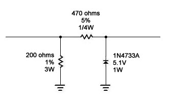
But now to protect the circuitry after that point, I had the idea to use a Zener diode. such that if the voltage goes above 5.1v, the diode clamps it there. I'm using a 1N4733A 5.1v zener rated for 1 watt. Using a 470 ohm resistor to limit current through the Zener and the subsequent load (an ADC, probably with an input buffer like an LM358 set up as a voltage follower to increase the impedance enough for the MCP3202 to sample reliably (slow sample rate, not at the high end of it's sample rate, so the effective input impedance should be a little more tolerant).
So - thinking that any voltage below the 5.1 volt level should remain relatively unaffected, I ran up the circuit below with a variable voltage bench supply. Measuring voltage across the 200 ohm resistor vs. across the Zener, things remain pretty close at the low end of the scale, about 0.05mV lower on the Zener than across teh rsisitor right up to about the 3.5v level across the input.
But then, the gap between Vr and Vz starts to widen, and when Vr gets to 5.24v, Vz is still at 4.24v, with a current flowing through the reverse biased Zener of 2.2mA. What's REALLY strange is that when my Vr is 15.0v, my Vz is 4.85v - still not even 5.0, let alone 5.1v.
Now the Zener is rated to take up to 49mA, but it just seems odd that the Vz never gets to 5.1v. I've tried a few different values of my zener current limiting resistor with the same basic result. I know I have to keep the Zener out of the Knee-region, but also make it work over my range of up to 24v across the device.
I thought this would be a simple solution for protecting the circuitry after the input resistor, but perhaps I'm on the wrong track. an unknown trust-level for the sensor - not knowing if it could ever fail to the full 24VDC into the loop - makes me want to protect my circuitry.
Am I doing something obviously wrong with the Zener, or, is there perhaps a better way to do this?
Thanks,
Dave
Referencing the little diagram below, my receiver has a 200 ohm 1% resistor. I've rated it for 3 watts since 24v into 200 ohms yields 120mA, or 2.88 watts, so that item is safe enough even at full loop voltage.
But now to protect the circuitry after that point, I had the idea to use a Zener diode. such that if the voltage goes above 5.1v, the diode clamps it there. I'm using a 1N4733A 5.1v zener rated for 1 watt. Using a 470 ohm resistor to limit current through the Zener and the subsequent load (an ADC, probably with an input buffer like an LM358 set up as a voltage follower to increase the impedance enough for the MCP3202 to sample reliably (slow sample rate, not at the high end of it's sample rate, so the effective input impedance should be a little more tolerant).
So - thinking that any voltage below the 5.1 volt level should remain relatively unaffected, I ran up the circuit below with a variable voltage bench supply. Measuring voltage across the 200 ohm resistor vs. across the Zener, things remain pretty close at the low end of the scale, about 0.05mV lower on the Zener than across teh rsisitor right up to about the 3.5v level across the input.
But then, the gap between Vr and Vz starts to widen, and when Vr gets to 5.24v, Vz is still at 4.24v, with a current flowing through the reverse biased Zener of 2.2mA. What's REALLY strange is that when my Vr is 15.0v, my Vz is 4.85v - still not even 5.0, let alone 5.1v.
Now the Zener is rated to take up to 49mA, but it just seems odd that the Vz never gets to 5.1v. I've tried a few different values of my zener current limiting resistor with the same basic result. I know I have to keep the Zener out of the Knee-region, but also make it work over my range of up to 24v across the device.
I thought this would be a simple solution for protecting the circuitry after the input resistor, but perhaps I'm on the wrong track. an unknown trust-level for the sensor - not knowing if it could ever fail to the full 24VDC into the loop - makes me want to protect my circuitry.
Am I doing something obviously wrong with the Zener, or, is there perhaps a better way to do this?
Thanks,
Dave

331 x 200 - 22K
Comments
Localroger - I'm not worried about a short in my receiver - I'm worried about a failure in the SENDING side that could drop the full 24vdc supply voltage onto the loop, which would put 24vdc across my 200 ohm resistor, and hence, on the subsequent circuitry. The loop supply is 24vdc rated 6.5 amps and supplies all of the sensors. So if one shorted internally, or, - more likely - one of the guys working in the plant hooks one up wrong and puts 24vdc right across my input... all the current limiting on Earth won't stop that! :-) So I want to make my input as bullet proof as possible.
I'm also looking at comparitors that could disconnect the input, as well as providing both over- and under-voltage alarms. Overvoltage could indicate a bad hookup or internally shorted sensor; undervoltage could indicate a disconnected or otherwise failed sensor, both of which would be useful functions to add to the existing system... but again - a fairly expensive add-on.
I know there has to be a way that's simple, cheap, and effective... :-)
Dave
I purchased some LTV-847 chips based on a forum post. I think they're used with MIDI projects. (I haven't used them myself yet.)
50 will cost $36.55 but I'd think single channel isolators would cost less.
Dave
OK
These have a max of 10mA
http://www.allelectronics.com/make-a-store/item/VTL5C4/VACTROL-R-ANALOG-OPTOISOLATOR/1.html
One end is an LED, the other is two leads from a CdS photocell
Instead of buying, you could make your own to experiment with.
PE
AEC' s description states "10mA max.", but the data sheet tells a different story.
http://www.datasheetarchive.com/dataframe.php?file=DSAP0021971.pdf&dir=Datasheets-111&part=VTL5C4#
The 47-ohm resistor will limit the current to about 25mA. Since, in this configuration, the LM317/resistor combo is a two-terminal device, current in has to equal current out, so it will not cause any inaccuracy. You do lose about 1.2V of compliance, though; but with a 24V supply, that should not be a problem.
-Phil
Sorry, missed the analog part.
Then - I could use the two clamping diodes with a 32mA fuse inline - since I have my Rsense value at a point where 20mA gives me 4.00 v across it, I have 1 volt over to use as a trip. Current shunting to Vdd exceeds 32ma, input fuse pops, and hopefully I have enough load on my 5v Vdd line that the momentary 24v spike at the input doesn't elevate my Vdd any.
Now I'm finding circuits that create a "Clamping Rail" - and this looks VERY interesting, since it would also prevent a higher current and voltage dump from elevating my Vdd line altogether. Diagram attached... anyone ever used a Clamping Rail circuit before?
Dave
So it turns out I was just overcomplicating things. A 220 ohm after my 200 ohm sense resistor, then the diode clamps. I'll never drop more than 110mA of 24 vdc onto my Vdd, and my 5v PS should have no problem sinking that (the 5v PS supplies 3A).
Problem solved. The input of the MCP3202 has a better profile than I was guessing looking at the the datasheet.
Thanks everyone for some great suggestions that got me thinking in new directions.
Dave
-Phil
Am I strange for really enjoying this whole process? :-)
Thanks,
Dave
Thanks,
Dave
At low frequency the error conditions are relaxed. It all comes down to the input circuit of the MCP3202 as depicted in figure 4.1 of the data sheet. There is a 20pF sampling capacitor that has to be charged up fully through 1kΩ plus whatever resistance you add on the outside. And that has to happen during two periods of the SPI clock, as depicted in figure 5.1. On the BASIC Stamp 2, 2e and 2pe, the SPI clock runs at 16.7kHz, so the sampling window is 120 microseconds. The time constant of 1kΩ with 20pF is 20ns. Even if you add another 1kΩ on the outside, the time constant is still <<120µs. The situation is more complicated with a faster Stamp, or with the Prop, where the SPI clock runs much faster or can be made to do so.
There is also a distinction to be made between the speed of the SPI clock and the frequency that readings have to be taken. If readings are taken at a low frequency it is possible to add a capacitor at the input pin >>20pf, and to increase the external input resistance between that capacitor and the outside world. The outside world has time to charge up the external capacitor, and the 20pF sampling capacitor samples a fraction of the charge. Say 20pF/0.1µF is a worst case sampling error of 1:5000.
I use a clamp circuit on my OWL data loggers where pins meet the outside world. It is partly to protect against wiring errors, also to protect against ESD. I use the SP720 or SP721 TVS array. Those provide multiple high speed (2ns) SCR clamps to the Vdd and Vss rails. The way I use it, each input connects to a pin of the TVS array via a resistor, and from there another resistor connects to the ADC or µP pin. I don't like to shunt current to the Vdd rail, so I use a PNP transistor with the base tied to a stiff voltage reference so that positive faults also shunt to ground. There are reference zeners with very sharp knees that kick in at around 10µA.
Sorry to throw a monkey wrench into this, but just because the power supply regulator can source 3A does not necessarily mean it can sink that much if any current. Most likely it cannot sink any current, so in order for clamping diodes to protect the circuit from an over voltage condition your circuit would have to draw at least 110mA
Kwinn - yes indeed, thanks for pointing that out, my error in wording. And with a chip count in this project of (so far) at least 54, plus a giant LED annunciator panel and a Spinneret server... I'm betting I'll hit that 110mA level at some point before I'm done!
Now to figure out how to best get the afore mentioned Spinneret Server to send the data to a remote server... email, POST... :-)
Thanks all!
Dave
Sorry to see this one so late! There are some analog optos in existence that are used in current loop applications.
Man, I hate it when I'm late to the party...