

QuadX source code for Hoverfly Open / Elev-8
 JasonDorie
Posts: 1,930
JasonDorie
Posts: 1,930
I keep saying I'm going to do it, so here it is.
This is my QuadX flight code for the Hoverfly Open board.
This includes the GroundStation software (and C# source). All the pins used by the HoverFly Open board are documented in the main source file (called "Main - HoverFlyOpen.spin").
This version uses the Gain channel the same way the HoverFly code does. Set the gain value on your transmitter to 20 or so as a starting point and increase it until it starts to oscillate, then back off a bit. The code is currently set up to use both sides of the gain switch - The positive side performs no gyro filtering, and the negative side runs a light low-pass filter on the gyro values, but the gain calculation is the same. I would actually recommend removing the filtering code and just having it let you choose between two different gain values to see which you like better.") The filtering seems to make the controls a little mushy. You should do everything you can to reduce vibration on your quad before resorting to noise filtering.
The filtering seems to make the controls a little mushy. You should do everything you can to reduce vibration on your quad before resorting to noise filtering.
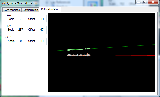
The included driver for the ITG3200 object has all the temperature drift values zeroed out. To calculate the proper ones for your board, plug your HoverFly board in to the USB connector, then run the GroundStation software and choose the "Drift Calculation" tab. With the board perfectly still, point a hair dryer or heat gun at it for a short time. You should see the gyro readings moving along a more or less straight line, and the program will line-fit your values and tell you the offset / slope numbers for each axis. Plug those in to the ITG-3200.pasm code at the end (it's well marked) and reload your HoverFly board with the result.

Questions & comments are welcome - I'm looking forward to feedback. Happy flying folks.
This is my QuadX flight code for the Hoverfly Open board.
This includes the GroundStation software (and C# source). All the pins used by the HoverFly Open board are documented in the main source file (called "Main - HoverFlyOpen.spin").
This version uses the Gain channel the same way the HoverFly code does. Set the gain value on your transmitter to 20 or so as a starting point and increase it until it starts to oscillate, then back off a bit. The code is currently set up to use both sides of the gain switch - The positive side performs no gyro filtering, and the negative side runs a light low-pass filter on the gyro values, but the gain calculation is the same. I would actually recommend removing the filtering code and just having it let you choose between two different gain values to see which you like better.
The included driver for the ITG3200 object has all the temperature drift values zeroed out. To calculate the proper ones for your board, plug your HoverFly board in to the USB connector, then run the GroundStation software and choose the "Drift Calculation" tab. With the board perfectly still, point a hair dryer or heat gun at it for a short time. You should see the gyro readings moving along a more or less straight line, and the program will line-fit your values and tell you the offset / slope numbers for each axis. Plug those in to the ITG-3200.pasm code at the end (it's well marked) and reload your HoverFly board with the result.
Questions & comments are welcome - I'm looking forward to feedback. Happy flying folks.
zip
171K
650 x 396 - 45K
Comments
As discussed, I am sending you a pair of my pcbs. This should make for a really cheap prop solution for those that want to play.
Here is a brief description of my pcbs on the other thread
http://forums.parallax.com/showthread.php/147891-Competing-QuadCopter-solutions?p=1186472&viewfull=1#post1186472
The power pcb on the left had a manufacturing error and was redone (pads omitted).
It is possible to drive Tri/Quad/Hex/Octal 'copters with these pcs. There are 8 channels of servo inputs (plus 2 spare) and the same for outputs. Each set of 8 are protected by series resistors (smt quad packs) and it was my intention to fit 5K. What are your current thoughts?
There is provision for 2 EEPROMS - can boot from either - why? So one can have code to copy new programs from the microSD card meaning a Propplug is not a requirement (lowers cost). The P30/31 circuit contains resistors for doing LF or FS USB emulation (with miniUSB connector). I did get Brad's LS USB code running so I thought it could be expanded. The SD could log flight info for later examination on a PC. There are a few other tricks, but I cannot recall them all.
The little pcb is about 1"sq and has gyro, accel, compass and pressure/temp chips. However, the price for these 10DOF pcbs have come down lately so they can be had from ebay quite cheaply. The QFN chips are difficult to hand assemble, so why bother. The main pcb has 3V3, 5V, GND and SDA and SCL connections for this, and two other mounting nc pins. Of course, you can just use the Wii Plus pcb scavenged from a Wii Plus controller like I did originally.
As I said, my aim was to make a really cheap set of pcbs and make them available either bare or assembled. I expect the bare pcbs (pwr and prop) to be <$5 (pair) and assembled (except header/servo pins - supplied unsoldered) to be <$20 (pair).
BTW I used a 1"sq tubing for my quadcopter and the X joiner - all available from the hardware store. There is an old QuadCopter thread where all this was explained. I haven't had time to pursue any of this
I only need one eeprom, as I've got a PropPlug. The SD card for logging could come in handy though. I had one on a quad two versions back, but crashed it. I keep meaning to hook it back up again, 'cause it was handy. A status LED or a small speaker is really useful. I have an arming sequence for my own quad so I don't accidentally start it on the bench. I use a tiny speaker for feedback, but a red/green LED would work just as well. (I realize the boards are done, but if you ever do another round...)
Looking forward to seeing it!
Jason
Thank you very much for posting this. I dug my ITG-3200 breakout board out of a box yesterday so I can test out your code. I have a HoverFly Sport board but it's on my hexacopter so I thought I'd try your code on a DIY board (I'm using one of these with a Prop on it).
When I tried to compile "Main-HoverflyOpen" I received a "Expected a subroutine name." error on line #571.
I'm guessing you're using a modified version of FullDuplexSerial. I'm hoping you'll either post the modified version let me know where I can find it.
I figure I can just change it to the "dec" method to get it to compile.
Thanks a bunch for posting this.
Another question for you. As I mentioned, I'm using SparkFun's ITG-3200 board. Do I need to make any changes to the board other than adding headers? I see there's a jumper on the bottom of the board to connect the CLK line to ground. From the product page:
Edit: After reading the datasheet on the ITG-3200, it looks pretty clear I should short the jumper. I'm tying the VIO to VDD (since the Prop's logic is the same as the gyro's VDD).
I'm planning on using the ITG-3200 on the Prop's I2C lines. Looking at your code I don't see a problem with this. It looks like the Prop reboots after any EEPROM writes so I shouldn't need to worry about the conflicting I2C drivers. Do you see any problem with using P28 & P29 for the gyro communication lines?
Hope you're having a good weekend.
BTW, HobbyKing has a much less expensive version of the ITG-3200 3205 breakout board. (Edit 3/27/13) I hadn't noticed the HobbyKing sensor is the ITG-3205 not the ITG-3200. I haven't figured out what the differences are between the two sensors.
I had just about decided the 3205 and 3200 were about the same device. I'll probably order a 3205 from HobbyKing with my next order.
I thought I'd mention, in case anyone else is using SparkFun's ITG3200 breakout board, the SparkFun board has one of the address pins pulled high so the SparkFun gyro's I2C address needs to be entered in to the gyro's driver.
Here's the change I made to use the $69 address instead of $68:
I still haven't flown with the new code yet. I'm trying to make sure everything is connected correctly since I'm not using HoverFly board.
Thanks again for posting your code Jason.
Is there a way to set the com port in your ground station program? I don't see it.
I hope it doesn't have a problem with high com port numbers (I'm using COM28 on my quad).
I noticed in your screenshot only the Y axis had a slope. Did you have the drift correction already configured for the X and Z axises in the PASM section when you ran your test?
All three axises on my gyro have about the same amount of slope (though the Y slope is negative).
Since I haven't been able to get your ground station software to work on my computer yet, I sent the raw gyro and temperature readings to the terminal and pasted the readings into a spreadsheet. This is what my graph looked like.
Column B is the X reading, F is the calculated line using the computed slope and intercept for the X axis. C and I are the Y graphs and D and L the Z.
I had the speed controllers plugged in which caused some vibrations (the motors would spin a little as they beeped). It's still pretty clear there's a linear relationship between the temperature and the output from the gyro. My graphs with the ESCs unpluged are a bit cleaner but don't have the same range as the graph above (I both cooled the board and heated it for this test).
Since there's extra time within the 250Hz read cycle, have you considered making multiple reads of the gyro and averaging them from within PASM?
I was just reading in the datasheet to see if there would be a problem reading from the sensor without a pause between reads and I see the sensor has several filter settings. It looks like you're not using any of these on-chip filters but are using software filters. Have you tried any of the on-chip filters?
If you haven't tried them, I may see if they make any difference once I'm airborne. I think I'm almost ready to fly now that I have some calibration data.
It looks like the drift calculations are the parameters that are hardest to adjust without the your ground station program. I figure I can tweak the PID and gain parameters from within the program.
I'm slowly feeling like I'm understanding the way your program works. I very much appreciate your willingness to share the code.
Replace Ports[0] with your "COM28".
Also, my apologies to those who've tried to compile the code and had the decd() method fail. I have modified my local version of FullDuplexSerial to include a method to print a decimal number with a reserved number of characters. You can just change the call from .decd( ) to .dec( ) and remove the 2nd parameter. I'll fix it and re-upload it when I get a chance.
No, I had mine zero'd when I ran the test. Every gyro is different. My first gyro only needed drift compensation on one axis. My second needed it on all three, with two being the same slope and one being negative (like yours). My most recent one has all three with slightly different slopes.
You probably don't need as much range as you got. My line fit code will lock in *very* quickly as soon as a trend is present, and a bit of noise, as long as its consistent noise, won't hurt it. With the GroundStation running you can watch the line fit change as you heat / cool the board, and the numbers stabilize pretty fast.
I'm not doing it on this one, but I have in the past. My first version actually took 2000 samples per second and did the SAR 3 in the cog. I can't tell if it made a difference or not. In my latest code, sampling the gyro, accel, and mag takes enough time that I had to lower the rate. I may try bumping it back up again just to see if it helps. The ITG 3200 can also do oversampling and low-pass filtering on its own, which I believe I'm actually using. If I'm not mistaken, it's set to do high-rate sampling (1Khz) and low pass it at 98Hz.
From the code:
                        mov     i2cAddr, #22
                        mov     i2cValue, #$18+2        'DLPF_FS (DLPF_CFG = 2, FS_SEL = 3) = 1Khz sample, 98Hz lowpass
                        call    #i2cWriteRegisterByte

                        mov     i2cAddr, #21
                        mov     i2cValue, #3            'SMPLRT_DIV = 3(+1) = 1KHz / 4 = 250Hz sample rate
                        call    #i2cWriteRegisterByte
I haven't verified this against the datasheet, but the comments claim that's what I'm doing.
Yeah, it's much easier with the GroundStation software, though you could do it from your set of sample data. Look at the source code for GroundStation, in the file LineFit.cs. The last function in there, ComputeLine(), is the one that computes the slope and intercept of the line from the samples. Each sample is a temperature, and x, y, z. The two sets of values it computes are exactly what you plug into the drift calculator in the ITG code. You can probably make Excel do the same math for you relatively easily.
Happy to share the code. It wouldn't be where it is without the help and code of many other people.
John
Since Jason hasn't answered I'll let you know what I think.
No Jason's code can't be used with GPS right now. I'd be surprised if he doesn't plan to include it as some point in the future.
The options listed on the ELEV-8 product page refer to the HoverFly boards. The HoverFly board with GPS is pretty expensive IIRC. Since the ELEV-8 uses normal hobby ESCs, you could use other controller boards with it.
I agree with Duane, I would be willing to bet, that some day Jason will add GPS to his quad.
Shawn
J
First of all - thank you so much for sharing your code with the community! The QuadX-code is, to me, an excellent introduction to the propeller chip.
So my fiancee gave me the Elev-8 for x-mas. This is my first encounter with the propeller chip so I pulled the documentation for the chip and the Spin-language/spin assemby, found some source code (yours) and started reading. I've had a lot of experience with different mcu's in the past, mostly ARM and PIC, so grasping the Propeller was fairly straight forward. Though one thing had me seriously confused..
In the ITG-3200 driver you explicitly write that the code assumes a 80 MHz clock. Later on you set _clkmode = xtal1 + pll8x and _xinfreq = 5MHz which, if I've understood the documentation correct, will give a system clock of 40 MHz instead of 80. What am I missing here? I first thought the 40 MHz referred to the hub clock since that runs in system clock/2 speed, but that doesn't seem to be the case either.
I'm sure that I'm just temporarily blind and that I'm missing something blatantly obvious but I would appreciate if you'd clear things up for me..
thanks in advance!
Benny
//Benny
Happy to hear you're having fun with it!
The source code for the firmware that ships on the Hoverfly Open is not available.
-Russ
This sounds like a good move.
-Russ
Will that be available as a board only? I recently got the ELEV-8 V2 Kit - No Flight Controller.
-dan
Of course! We're just doing the layout now so we're already getting started. I'll be sure that the Parallax Flight Controller (code name Navig8) specification is posted here on the forums for feedback, too. What you may want to do is start with the KK board and replace it with the Parallax Navig8 when it is ready.
I promise to deliver you the most open, useful, and warrantied flight controller for the ELEV-8 V2.
Ken Gracey
HI, I have the same problem, could you fix it ?
The DecD method is a custom one I added which outputs a fixed number of digits, regardless of the length of the number, making it easier to read values that are changing quickly, but it's not a functional requirement for the code.