

LSM303DLHC Tilt Compensated Compass Help
 waymond91
Posts: 15
waymond91
Posts: 15
Hello All,
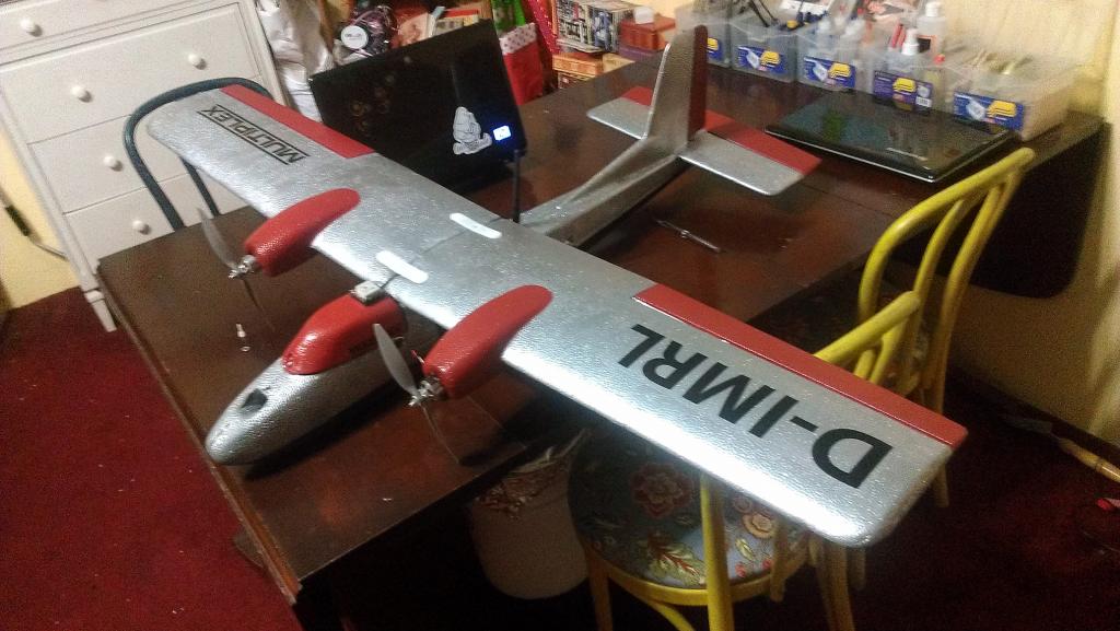
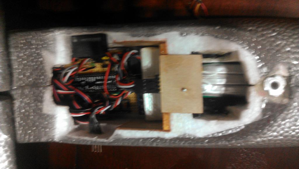
I have been working on an propeller based autopilot for a while now, and things have been coming along great. Although I was nervous about the lack of interrupts, the faster speed and multiple cogs have made timing the program efficient. I purchased the Pololu brand IMU v2 for $50, and my only complaint might be that the board is TOO small. I am implementing a complementary filter to filter all vibration noise, and it seems to be working just fine.
I am able to set the attitude of the plane using a simple PID loop, and I am receiving data back from the airplane to my laptop via xbee. The only problem is: I cannot tilt-compensate the compass module.
The LSM303DLHC contains both an accelerometer and magnetometer (I assume specifically for this purpose!) I am able to read the whole sensor using the I2C bus.
I have tried both the algorithms found at these websites:
https://www.loveelectronics.co.uk/Tutorials/13/tilt-compensated-compass-arduino-tutorial
https://gist.github.com/timtrueman/322555
Before implementing the tilt-compensation, I normalize the magnetometer values by find the total magnitude:
r = sqrt( magX ^2 + magY^2 + magZ^2)
and then divinding each component by magnitude.
However, after using my atan2 function, I do not get a full 360 degrees!!
I don't know if my IMU is orientated correctly:
X-axis -> towards nose of plane
Y-axis -> towards right wingtip
Z-axis -> downwards
While this reference frame is used in the first link above ^^ it is not what I am used to from math class lol
My yaw value stays center at about 170 degrees and -170. It actually changes very little as I spin the plane horizontally, however, the value scales up and down as I change the pitch and roll of the plane.
If i don't normalize the magnetometer vectors, I get a value between 60-120 for my yaw while spinning it level, but again is not tilt-compensated.
What is more confusing, if i use atan2(mz,mx) and add 360 if its less than 0, i get a full 360 degrees while spinning the plane horizontally. The only problem is that its not tilt compensated...
Any ideas on this one guys? Has anyone succesfully tilt compensated this magnetometer before? I do not understand why this algorithm is not working, we only care about the planes direction in the xy plane, so using atan2 makes sense enough.
Here is a clip of the code I am using (I apologize ahead of time, float math is more troublesome then i would like on the propeller chip)::


THANKS FOR ANY HELP!!!
I have been working on an propeller based autopilot for a while now, and things have been coming along great. Although I was nervous about the lack of interrupts, the faster speed and multiple cogs have made timing the program efficient. I purchased the Pololu brand IMU v2 for $50, and my only complaint might be that the board is TOO small. I am implementing a complementary filter to filter all vibration noise, and it seems to be working just fine.
I am able to set the attitude of the plane using a simple PID loop, and I am receiving data back from the airplane to my laptop via xbee. The only problem is: I cannot tilt-compensate the compass module.
The LSM303DLHC contains both an accelerometer and magnetometer (I assume specifically for this purpose!) I am able to read the whole sensor using the I2C bus.
I have tried both the algorithms found at these websites:
https://www.loveelectronics.co.uk/Tutorials/13/tilt-compensated-compass-arduino-tutorial
https://gist.github.com/timtrueman/322555
Before implementing the tilt-compensation, I normalize the magnetometer values by find the total magnitude:
r = sqrt( magX ^2 + magY^2 + magZ^2)
and then divinding each component by magnitude.
However, after using my atan2 function, I do not get a full 360 degrees!!
I don't know if my IMU is orientated correctly:
X-axis -> towards nose of plane
Y-axis -> towards right wingtip
Z-axis -> downwards
While this reference frame is used in the first link above ^^ it is not what I am used to from math class lol
My yaw value stays center at about 170 degrees and -170. It actually changes very little as I spin the plane horizontally, however, the value scales up and down as I change the pitch and roll of the plane.
If i don't normalize the magnetometer vectors, I get a value between 60-120 for my yaw while spinning it level, but again is not tilt-compensated.
What is more confusing, if i use atan2(mz,mx) and add 360 if its less than 0, i get a full 360 degrees while spinning the plane horizontally. The only problem is that its not tilt compensated...
Any ideas on this one guys? Has anyone succesfully tilt compensated this magnetometer before? I do not understand why this algorithm is not working, we only care about the planes direction in the xy plane, so using atan2 makes sense enough.
Here is a clip of the code I am using (I apologize ahead of time, float math is more troublesome then i would like on the propeller chip)::
mx := fm.ffloat(IMU.getMX)
my := fm.ffloat(IMU.getMY)
mz := fm.ffloat(IMU.getMZ)
mv := fm.fsqr(fm.fadd(fm.fadd(fm.fmul(mx,mx),fm.fmul(my,my)),fm.fmul(mz,mz)))


pitchRad := fm.radians(pitch)
rollRad := fm.radians(roll)


mx := fm.fdiv(mx,mv)
my := fm.fdiv(my,mv)
mz := fm.fdiv(mz,mv)


magY := fm.FSub(fm.fadd(fm.fmul(fm.fmul(fm.cos(pitchRad),mx),fm.sin(pitchRad)),fm.fmul(fm.cos(rollRad),my)),fm.fmul(fm.fmul(fm.sin(rollRad),mz),fm.cos(pitchRad)))


//sorry for how ugly this term is ^^^


magX := fm.fadd(fm.fmul(fm.cos(pitchRad),mx),fm.fmul(fm.sin(pitchRad),mz))
yaw := fm.degrees(atan2(magY, magX))


PRI atan2(_y, _x) | _z, atan       //this is my atan2 function


if _x == 0.0
if _y > 0.0
return(PIBY2_FLOAT)
if _y == 0.0
return(0.0)
else
return(fm.fneg(PIBY2_FLOAT))


_z := fm.fdiv(_y, _x)
if fm.fabs(_z) < 1.0
atan := fm.fdiv(_z, fm.fadd(1.0,fm.fmul(fm.fmul(0.28, _z), _z)))


if _x < 0.0
if _y < 0.0
return(fm.fsub(atan, PI_FLOAT))
else
return(fm.fadd(atan, PI_FLOAT))


else
atan := fm.fsub(PIBY2_FLOAT, fm.fdiv(_z , fm.fadd(fm.fmul(_z, _z), 0.28)))
if _y < 0.0
return(fm.fsub(atan, PI_FLOAT))


return(atan)
THANKS FOR ANY HELP!!!
Comments
I am actually working on the same thing, but I am using a HMC5883L mag and a ADXL345 ACC. I found your thread while searching on how to do the exact same thing. I do not have much info for you I am sorry. I do not think you have to normalize the magnetometer vectors. I ran the mY and mX values through the ATan2 function without normalizing them to get my heading and it seemed to work. I am not not quite as far as you are, I am still fighting to get an I2C routine running that I like, to read the sensors. https://www.loveelectronics.co.uk/Tu...duino-tutorial This is the exact same link I found for an example on how to implement tilt compensation. I will post more when I have more info, hopefully we can get this figured out.
Good Luck
Shawn
I have been playing with tilt compensation almost all day now. I should be at work, but I was sick as a dog this morning. I have a hard time following my own code let alone other peoples code. I managed to put together a program using the full float32 object and the equations found at this link you posted above.https://www.loveelectronics.co.uk/Tu...duino-tutorial It did not work the first couple of times I tried it. After I fixed my equation errors I had to flip my acc axis's around. I was getting compass headings but not tilt compensation until I swapped them. In your equation try swapping sin(pitchRad) with sin(rollRad) and also cos(pitchRad) and cos(pitchRad). If your equations are right this will probably fix your problem.
I also did not normalize the magnetometer readings. I do not think they need normalized since they are vectors. You can run them through Atan2 and get an angle,which you already Know I ran the raw values mX, mY, and mZ through a low pass filter and then plugged them straight into the tilt compensation equation. I also ran my roll and pitch values through a low pass filter. When I add this to my quad I probably will not use the output of my ACC for the tilt compensation. I will probably use the output of my Pitch and Roll complimentary filter which is less noisy.
Shawn
Thank you for the reply! I tried swapping pitch and roll as you say, but it is still not tilt resistant. It could be that my equation is simply not right, I will try to break it down into simpler terms and then add them up. Looking back right now I am finding a couple mistakes.
In the meantime, when i simply use
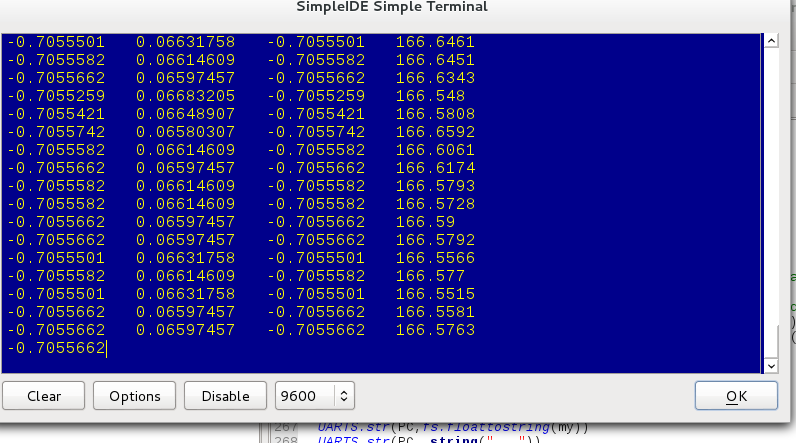
yaw := fm.atan2(my,mx)
with unfiltered un-normalized values, all my values for yaw are between 60 degrees to about 110. So even if I did tilt-compensate magY and magX, i still would not have a full 360 degrees of motion???
I just got out of class and I intend to work on this until i get an acceptable solution :P
What I like about using the propeller for this project, because it is faster than an arduino, I can set tao for the complementary filter upwards of .995 and still not see any drift because it calculates so fast. I have not attempted to filter the magnetometer yet because I have not extracted any meaningful values yet.
I anticipate there will only be noise when the motor is running, not due to vibration but to electrical interference. If this is the case i will just use the complementary filter again with the gyroscope about the z-axis.
If thats not enough I will try to pass my esc values through the propeller chip so I have an idea how much current the motor is drawing. I imagine this will be much harder for you because you have four times as many motor lines on a quad :P
pitchRad := fm.radians(roll) rollRad := fm.radians(pitch) 'mx := fm.fdiv(mx,mv) 'my := fm.fdiv(my,mv) 'mz := fm.fdiv(mz,mv) a := fm.fmul(fm.fmul(fm.sin(pitchRad),mx),fm.sin(pitchRad)) b := fm.fmul(fm.cos(rollRad),my) c := fm.fmul(fm.fmul(fm.sin(rollRad),mz),fm.cos(pitchRad)) magY := fm.fsub(fm.fadd(a,b),c) magX := fm.fadd(fm.fmul(fm.cos(pitchRad),mx),fm.fmul(fm.sin(pitchRad),mz)) yaw := fm.degrees(fm.atan2(magY,magX)) if yaw < 0 yaw := fm.fadd(yaw, 360.0) UARTS.str(PC,fs.floattostring(fm.cos(pitchrad))) UARTS.str(PC, string(" ")) UARTS.str(PC,fs.floattostring(fm.sin(pitchRad))) UARTS.str(PC, string(" ")) UARTS.str(PC,fs.floattostring(yaw))I am not real sure, I guess there is more learning to do.
Shawn
Shawn
Are you making any prgress? I think I have it kind of working. The values are noisy and the mag is not calibrated. Swapping my pitch and roll in the equation did fix the problem. My other problem was that I was sending Pitch and Roll values into the compensation equation in degrees instead of radians. Here is the program I wrote if you want to take a look. It is by no means elegant. I have a routine in the program that I tried to break down the compensation equation piece by piece. It displays raw acc and mag values. It displays pitch and roll angles. And finally it displays non-compensated and compensated heading(azimuth) values.
The compensated heading does very as the board is tilted but it is by no means as bad as the non compensated heading. I have a sneaking suspicion that this is because of noise from the mag and acc and possibly the fact that it is not calibrated. Calibration of the Magnetometer is probably the next thing I will try and mess with.
I think the way to implement this would be to use the pitch and roll values from your complimentary filter that combines your Gyro and ACC values. Then when you have a compensated MAG value, you would want to combine this with the Gyro Z axis via another complimentary filter. At least this is what I am going to try.
mag tilt comp with acc V3.0.zip
Shawn
Sorry, I got a little sidetracked today. I still do not have it working correctly.
I am using the Pololu IMU 9 v2, and both the gyro, accel, and compass are oriented the same way, as described before.
Also, my current system describes a positive pitch when the plane noses up, and a positive roll when the right wingtip rises.
Is this consistent with your setup?
Thank you for uploading your code! I am about to go through it.
In the meantime, after talking to some people on DIY drones, I found this article. I think it may explain some of the issues involved with calibrating magnetometers:
http://www.sensorsmag.com/sensors/motion-velocity-displacement/compensating-tilt-hard-iron-and-soft-iron-effects-6475
Do all three of your sensors go positive when you pitch the nose up, and positive roll when the right wingtip rises? You can still have the axis aligned but the signs from sensor to sensor may be backwards. On my present setup I had to invert my gyro data on the roll axis so that it goes positive when my acc goes positive but the axis's were aligned. If that makes sense, from what I was reading last night I think the same goes for the mag.
Have you got the device to read 0 - 360 degrees yet? I believe it should do this whether its calibrated or not, the down fall will be it will not read a true circle it will be some sort of eclipse. I am not familiar with the HMC5882L let alone the LSM303DLHC. Have you triple checked you configuration settings for the device. I was getting an overflow on mine and had to increase the gain.
My final thought is that once your Flight controller is tilted past 40 to 45 degrees in any direction the complimentary filter no longer reads accurate angles of pitch and roll. This means that your heading on your MAG will start to drift. I think this is why the guys that have been playing with for some time have switched over to DCM.
I will probably play with it some more this weekend, I think I have been working on this quad for almost a year.