How to make a XY Plotter/Printer/Scanner from recycled parts
This idea has been cooking in my workshop for a looong time now....
I have always wanted a 2D scanning/printing area for various projects.
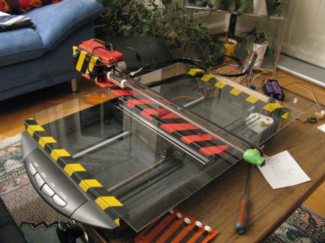
So i present here a system which is made from a Hacked recycled scanner bed and a dead printer..

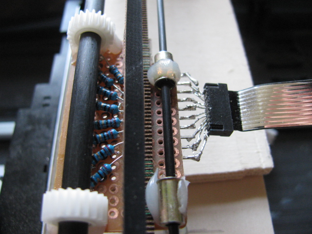
The system uses a Propeller mcu and only uses 2x4 outputs for Stepper motors, 4 inputs for buttons, and 8 outputs for UV carriage ...... (so a bit of redundancy for "Z" axis should it be required)
[video=youtube_share;ynOerOdcO-g]
It consists of a "Y" axis made from a stripped down Scanner (keeping the Stepper motor, limit switches and control buttons)
The "X" axis is from a defunct printer .... stepper motor, various cogs and connectors)
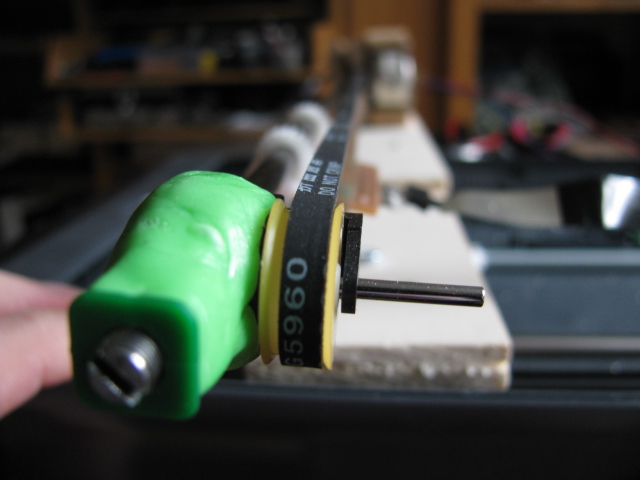
Below you see the Belt tensioner for the "X" axis.
Its a fine threaded screw which pushes against the carbon fibre rod which is part of the support arm.
This allows pretty fine control over the belt tension.

Presently i have mounted 8 UV Leds for fun, means that i can write messages on the screen....indefinitely.
Its a chance to tune and test the durability of the software & hardware .

The plan is to replace the UV leds with a UV laser and then another quite different story begins.....
I have always wanted a 2D scanning/printing area for various projects.
So i present here a system which is made from a Hacked recycled scanner bed and a dead printer..

The system uses a Propeller mcu and only uses 2x4 outputs for Stepper motors, 4 inputs for buttons, and 8 outputs for UV carriage ...... (so a bit of redundancy for "Z" axis should it be required)
[video=youtube_share;ynOerOdcO-g]

It consists of a "Y" axis made from a stripped down Scanner (keeping the Stepper motor, limit switches and control buttons)
The "X" axis is from a defunct printer .... stepper motor, various cogs and connectors)
Below you see the Belt tensioner for the "X" axis.
Its a fine threaded screw which pushes against the carbon fibre rod which is part of the support arm.
This allows pretty fine control over the belt tension.

Presently i have mounted 8 UV Leds for fun, means that i can write messages on the screen....indefinitely.
Its a chance to tune and test the durability of the software & hardware .

The plan is to replace the UV leds with a UV laser and then another quite different story begins.....


Comments
A multi-prop setup might be just the ticket.
Do you plan to do micro-machining with the laser?
Looks like a really fun project!
sm
Great hack....
Gives me ideas... lots of ideas... now if only I had the $$$ to fund these ideas...
I digress... Anyway, great project!
Fred
By my calculation its would be a breeze to add extra Z-axis (not with my mechanics above though)
My biggest io overhead is the 8UV carriage ...... drive one laser and whooop-de-dooodah extra io's.
I have seen blueray lasers being used....Hmmmm