

About Parallax 433 MHz RF Transceiver. Increasing RF range !!. Please, help.
 markuster
Posts: 184
markuster
Posts: 184
Hi,
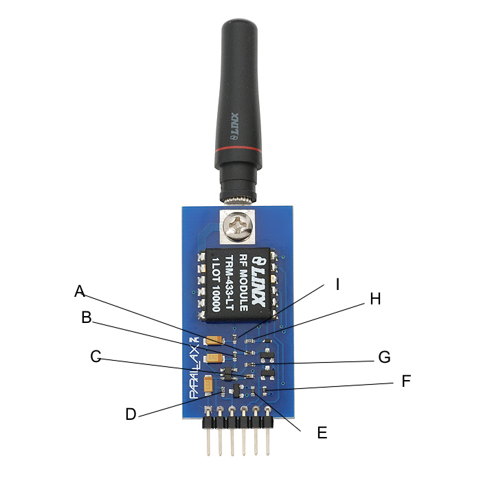
I need to increase the RF range of the item 433 MHz RF Transceiver from Parallax.
( Please see attached)
I understand that I need just to replace one of these little resistors by a little
wire.
But my problem is that I don't know which resistor must be replaced.
Please help.
Thanks,
I need to increase the RF range of the item 433 MHz RF Transceiver from Parallax.
( Please see attached)
I understand that I need just to replace one of these little resistors by a little
wire.
But my problem is that I don't know which resistor must be replaced.
Please help.
Thanks,
700 x 700 - 79K
Comments
No problem , The RF will be inside a metal case , for this reason I need to increase range. Do you have the squematics ?
Thanks, again.
Providing schematics with the change would be supporting the modification. These modules have been certified by the FCC in their current form, and if you make modifications you may be running an illegal transmitter. Even if it is in a metal case.
I Don't need schematics with the changes. I just need the original schematics , because I don't have
any schematics. I tried to download from the Parallax website but I can't find the newest schematics .
Please help.
Thanks.
Mr. Savage does not mean to be a brute about this, it's just that SRLM is right: before a company can sell a transmitter, they need to get the device FCC certified in its present form. Mr. Savage is not even allowed to tell you how to make modifications, because that might be construed as offering a kit which has not been certified and probably couldn't get certification. Anyone telling you how to modify it, might also be in violation of the law - and you'd be astonished at how persnickety the FCC can be about people using too much power on the wrong wavelengths without the right licenses, etc.
My english is not good. I don't know if I am explaining my self.
I will try to ask again but using other words:
I would like to know if there is schematics in order to understand how can I modified the circuit.
I tried to use the transeiver inside a metal box and the range was about 6 feet only.
I don't need a mile range , I just need about 50 feet range. Even with 30 feet range I will be happy.
Don't worry , I will not broke any kind of FCC law. I will just set the resistor to 50 feet range as a maximum
range.
But I need the schematics in order to tried to understand the product becasue I want to know if I can reduce the comsuption
too.
Thanks again,
Well, I can't help you find a schematic. My recommendation would be to follow the traces, and reverse engineer the schematic yourself. That, combined with the datasheets for the various chips, is probably all you need.
But be aware that the FCC requirements are based on transmission strength, not "range". I don't know if the power is measured outside the device or not, but any modifications will likely require re-certification.
I doubt (and hope) this isn't true.
To increase the power of the device you'd want to reduce the resistance of R2. Using a piece of wire instead of a resistor will set the module to its maximum power.
Now I just set back and wait to be carted off to jail.
As others have mentioned, you can get in trouble with the FCC if your device outputs too strong of a signal. I do agree with the FCC rules and think you should abide by them. I just really dislike the notion that some information should be illegal to share.
I feel confident passing along information available in the Lynx datasheet wont get be sent to jail.
Yeah, you're right. No jail. Nothing like that. You'll just have creepy old guys like this one hanging around outside your house at night:
Thanks for helping
A piece of a solid copper wire should work fine.