

Inductive Spark Plug Wire Tachometer - Signal Transformation Help
 sirhannick
Posts: 4
sirhannick
Posts: 4
I am working on a new project that is going to be a universal tachometer for small engines. It will use a wire wrapped several time around the spark plug wire. The signal needs to be converted to a cleaner digital signal that I can use to be picked up by the Basic Stamp. I'm not having issues with the coding, but rather the circuitry necessary to clean up the signal I'm getting from the spark plug wire.
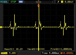
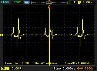
I have a digital scope so I have no problem trying out different designs and then posting the results they provide. I have attached two images of what the signal is that I'm getting right now.

I've tried various combinations of diodes, capacitors, & resistors, but none has given me a signal I can really work with. Does anyone have experience with this? Any ideas?
There was a lot of discussion here:
http://www.eng-tips.com/viewthread.cfm?qid=320604
However, I don't think they ever 100% figure it out. I'm not sure if isolated power or an opto-isolator are necessary as discussed in that thread.
If I get this part figured out I have plans to turn this into an hour meter with LCD screen, maintenance monitor, and option to add more sensors.
I have a digital scope so I have no problem trying out different designs and then posting the results they provide. I have attached two images of what the signal is that I'm getting right now.
I've tried various combinations of diodes, capacitors, & resistors, but none has given me a signal I can really work with. Does anyone have experience with this? Any ideas?
There was a lot of discussion here:
http://www.eng-tips.com/viewthread.cfm?qid=320604
However, I don't think they ever 100% figure it out. I'm not sure if isolated power or an opto-isolator are necessary as discussed in that thread.
If I get this part figured out I have plans to turn this into an hour meter with LCD screen, maintenance monitor, and option to add more sensors.


Comments
I'm gonna guess you'll only need the positive "spike" as shown in the attached pictures, correct?
To do that, a series diode such as 1N4001 (around 50 PIV) should do the trick.
Then, the remaining "spike" will need to be attenuated as some appear to go as high as 20V? Yes? Inputting that level of signal into a Basic Stamp will destroy it. A simple voltage divider should help there. You could use a Schmitt trigger device in between the divider and Stamp to help clean up the signal.
Did that make any sense?
Circuit Used:
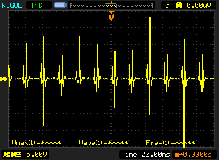
Here is a screenshot of the simple Schmitt I just tried:
The Schmitt is having a hard time picking what to trigger off of. If I zoom in on one of the digital "on" peaks, it's not solid, it turns on and off many times during it. I forgot to take a pic of that so it's hard to explain.
Another issue is the signal we're dealing with is VERY low current, so anything I do to it could change the signal.
Tomorrow I will try adding a diode to the circuit. Is there also somewhere I could add a capacitor to help the 555 stay on during it's on periods? The approximate frequency that should be the end result is 50 hertz (3000 RPM). There is approximately 20ms between sparks. I hope this information helps.
Thank you everyone for your help so far.
OK - you'll have to decide what part of the whole signal is the most important. I'm guessing you're most interested in the large positive peaks.
But what is to be done with all the "noise", right?
You could use a comparator with one input receiving the sensed signal, and the other input would receive a manually set DC voltage. This "set voltage" would become a threshold level; with the input signal less than the threshold level, the comparator output remains in-state. When the input signal rises above the threshold, the comparator output will change its state.
Works like a charm - use this type of circuit all the time in the equipment I support.
There's some nifty info about comparators here:
http://www.linuxfromscratch.dk/?page=comparator
The zener clamps the incoming signal between -0.6V and +5.6V. The diode charges the cap to 5.0V, which gets discharged more slowly through the parallel resistor. Combined with the Schmitt trigger, you get a one-shot of sorts.
If the hysteresis band of the Schmitt trigger is too narrow, you can make your own, with a wider band, from a comparator and some resistors.
-Phil
http://home.cogeco.ca/~rpaisley4/LM555.html#2
There's a great chart as well as calculator that page that helps you select the correct RC values. I chose a 470K ohm resistor and a 3300pF capacitor. According to the calculator that will give me a 17ms pulse. Here's the result of the circuit:
Phil-
Thank you for your recommendation. That is the other type of approach I've seen on various sites. Some also throw in a transistor. I may try it out if the 555 timer approach falls through.
I will post my progress on this thread to attempt to document this all.
Something you must keep in mind is that the pulse width from the 555 is fixed regardless of trigger frequency. A small 4 cycle engine has a typical top governed speed of 3600 rpm. That's 60hz which has a 16.67ms period, which is awfully close to your calculated pulse width from the 555. 2 cycle speeds are even higher which won't allow you to use this method. When your trigger period is above your pulse width of the 555, you are just going to keep retriggering and the output won't change state.
Have you considered doing your signal conditioning in software? Use could use a 5.1v zener in parallel with the input to quench the spikes. Use a debounce routine to read the input and delay long enough to trigger on the next pulse as opposed to part of a single pulse. You'd have to modify the pulse width of the debounce based on rpm to get around the problem you have with doing it in hardware with the 555.
I guess it all depends on what you want your design to be able to work with, engine wise, since that dictates the input parameters you must meet. Good luck!
What you are saying is completely true. However, for my specific application that pulse width works fine. I was able to get my stamp to give me a valid RPM output to my computer for a quick test this past weekend. My lawn mower was running around 3000rpm.
Now I am going to work on making a small enclosure with 8x2 character display & 4-6 buttons. As I make progress I will try to compile a parts list and share my schematics, code, & so forth. My goal is to make this into a unit no larger than 3x2x1 although smaller would be nice. This would just be for my first completed unit. Eventually I would move to a PIC or maybe a SMT OEM BS2px. It all comes down to cost.
I would be very interested to disassemble a retail tachometer/hourmeter unit I purchased on Amazon that claims to be capable of 0-99,999 RPM:
http://www.amazon.com/Tachometer-Kawasaki-Motorcycle-Generator-Snowmobile/
I have it installed on my father-in-law's snow blower and it seems to function decently. The RPM values are not exactly stable, but it works well as an hour meter. For the price it's great.
The type of pick-up wire you use to wrap arround the plug wire matters quite a bit. Wrapping your pick-up wire more than once provides more than one pick-up signal semi-simultaneously, additionally if you are using stranded wire for pick-up you only amplify the problem. You should be able to clean up your source signal by using a single wrap with a 6 to 8 gauge solid wire or magnetic block similar to what you would find in a commercially available timing light.