Problem executing programs on personal propeller board design
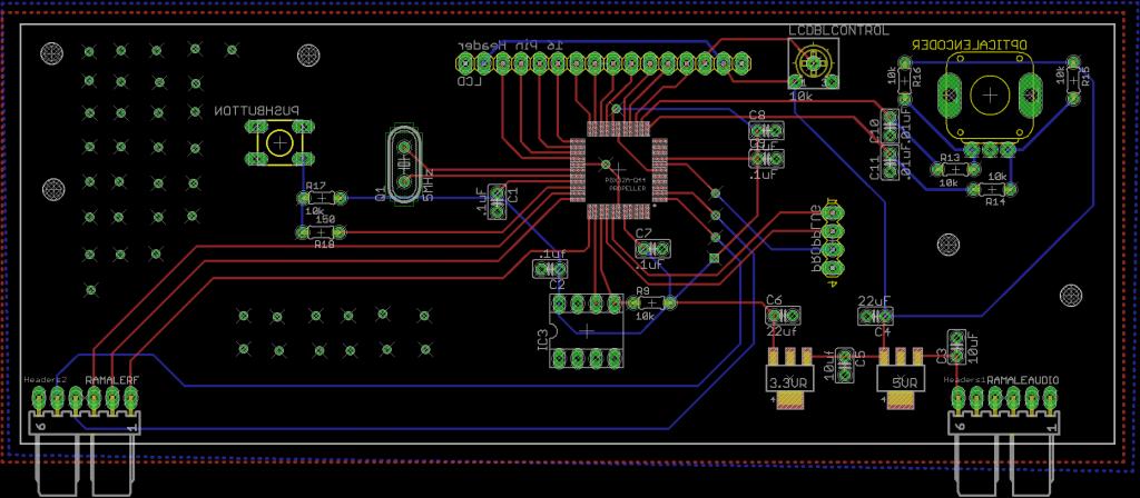
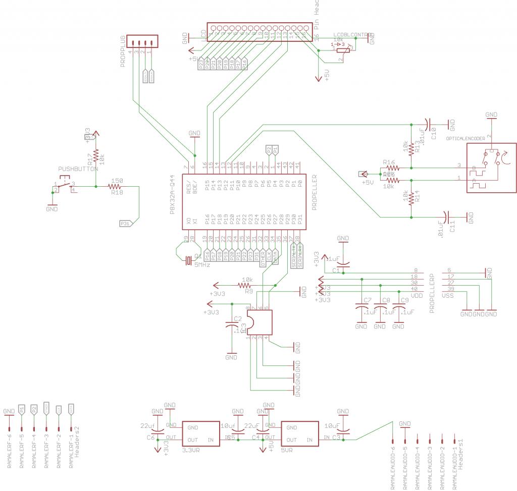
I have designed a board using the propeller Q44 package, but I'm having problems running programs. I am attaching pictures of both my schematic and board layout/design. Propeller tool recognizes both the prop chip and loads the program to the EEPROM (at least it says it is) but then fails to run the programs. Will you please take a look and see if you can find any errors in my design.

Thanks,
Kendall


Thanks,
Kendall


Comments
This is a problem that occurs when there's a significant current flow through the power grid on the chip itself when there's inadequate bypassing of all the power and ground leads for the chip and when there is a missing connection to one of the Vdd or Vss pins of the chip. As a result, there may be transient voltage drops across the chip large enough to damage whatever is most vulnerable, usually the PLL multiplexor that selects the subharmonic of the PLL output to be used for the system clock. The downloading and EEPROM writing code uses the Prop's internal fast RC clock (RCFAST) which doesn't use the PLL. When the loaded program attempts to switch to the crystal controlled clock, the clock stops working and the program doesn't run. Unfortunately, most code requires a stable accurate clock derived from the crystal oscillator, particularly for serial I/O or video output. Try hooking up an LED to one of the unused I/O pins and write a simple program to blink the LED in a specific pattern using "_CLKMODE = RCFAST" and "_CLKFREQ = 12_000_000". The actual frequency may be off quite a bit, but the program should run. Look at the board layout for any of Parallax's boards, particularly the power bypassing and the connections among the Vdd and Vss pins for good examples of how to avoid this if that's what happened.
Thank you!! Yeah this was my first design and I tried to go by the schematics for both the professional board and protoboard designs. I unfortunately have all four voltage pins wired separately with .1uF bypass caps, and I had a feeling all my grounds didn't get connected correctly. I'm using 8mil traces under the chip, but I don't see them on my fabricated pcb. I compared pin voltages on the professional board and my board to each pin and they came out exactly the same with the exception of the BOE and RESN pins. I thought that may be where the problem was. I also used the same voltage regulators found on the one of the propeller prebuilt board schematics I think they are LM2987s (3.3v and 5v) however the power supply I was using to power this board was pushing a current of 2.5Amps. I probably should've submitted these designs on this forum before sending the board os off for production. I guess I'lll have to do some major trace scraping and rewiring before putting the next one together.
I'll try the LED code momentarily.
Any other suggestions on how I can fix these problems without having to throw away 3 other copies of this PCB? It was for a school project (due tomorrow) and I imagine the purchasing folks and department heads aren't going to be too pleased with me.
THANK YOU SOOOOO MUCH btw on this information!
Kendall
2) Ideally, you'd have a 0.1uF SMT bypass cap on each side of the package, close to the package itself. Again, look at something like the Demo Board, ProtoBoard or Prop BOE for an example of proper layout.
3) Make sure any cross-connect traces under the chip are actually connected to the proper pins. Use a copper fill for VSS under the chip ... better than just traces for connecting the Vss pins
4) If the problem is that you've left off one of the Vdd or Vss connections, you can use a jumper wire ... typically some wirewrap wire from RadioShack. It's very fine and solders well.
-Phil
traces allows much more voltage bounce. At the very least ensure traces between chip supply pins and the nearest
decoupling capacitor are wide and short and run above/below the ground plane as much as possible. For the ground
connections a ground plane is clearly the best approach so long as it isn't too fragmented (issue with 2-layer)
With two-sided board the simplest option is to mount 4 decoupling capacitors on the underside directly
below each Vdd pin and take a via directly between pin and cap. If you are using tiny SMT caps they can go on the
topside without eating away too much board area (I tend to stay at 0805 as minimum size)
Its not clear to me that your board isn't working though as you seem to have the same problems on a Parallax
board...
Did you try the experiment Mike suggested, to run a simple test program on RCslow? If that works, you might also try running it with crystal at 5MHz without the PLL enabled.
You board photo shows a trace from pin6 BOE to pin17 Vss but no via to ground, and no connection at all to pin5 Vss. To remedy that, you might drill a hole through the board to the ground plane and attach a fine wire through to pins 5 and solder bridge to pin 6.