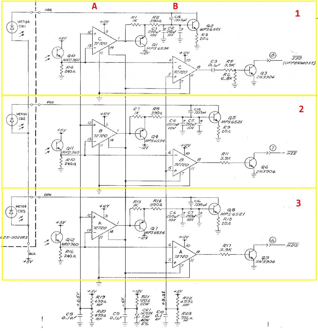
IR Detector schematic for guettomusick
 kwinn
Posts: 8,697
@guettomusick
Here is the schematic you requested along with a little information.
The op amps and associated circuit in column A are used to control the LED current so that the emitter voltage of the phototransistors are at 2.5V.
The op amps and associated transistor in column B pull the transistor outputs low when a tube passes in front of the sensor.
The schematic shows 3 almost identical detector circuits, the only difference being that the output of circuit 1 produces a short pulse that is used to latch the state of the 3 sensors into some TTL flip-flops.
The circuits at the bottom provide -6V and bias voltages to the op amps.
This circuit is from a very old piece of equipment so the op amps and transistors may not be available. Almost any general purpose op amp and small signal transistors should work in this circuit. I have used LM741, LM747, and LM358 op amps along with 2N3904 and 2N3906 transistors with no problems or changes required.


