

some issues with parallax Xbee 5V/3.3V adapter
 Sarah_Lafi
Posts: 7
Sarah_Lafi
Posts: 7
Hi every one
I'm working on parallex's xbee
This is the kit that I am using..http://www.amazon.com/Parallax-XBee-Wireless-Pack-Micro-controller/dp/B00B6SF2C6
It has two xbee , 1 usb adapter and 1 5V/3.3V adapter. I'm wondering about many things regards the 5V/3.3V adapter.
First, when I tried to connect Vcc pin of the board directly to a 3.3 volt, the adaptor does not power on. But when I connect the 5 volt to Vdd, it works.
Is this normal? or my board or xbee has a problem?
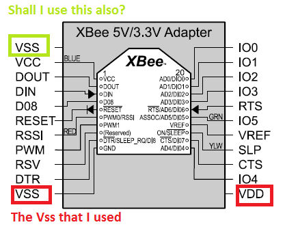
And which Vss pin shall I use? I used pin#11 but the board also has another Vss pin. shall I connect both?
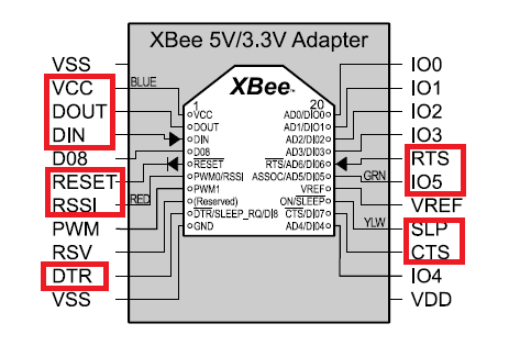
This is the pin out of the board that I am talking about.

Second, I noticed that the xbee tx LED which is in the board is mostly ON. although I am not connecting any wire to Dout or Din pins! I'am wondering what does the xbee transmit without connecting any thing to Din and Dout!
And the last thing is that when I tested the connectivity between the pin out of the xbee and the pin out of the board, I found that some pins are not connected ..
Is it normal?
This pictures below shows those pins that are not connected. Even the xbee usb adapter has some. Is this because of the internal circuit of the board... I will come up with the same picture for usb adapter soon ...
That is all... Waiting your help
I'm working on parallex's xbee
This is the kit that I am using..http://www.amazon.com/Parallax-XBee-Wireless-Pack-Micro-controller/dp/B00B6SF2C6
It has two xbee , 1 usb adapter and 1 5V/3.3V adapter. I'm wondering about many things regards the 5V/3.3V adapter.
First, when I tried to connect Vcc pin of the board directly to a 3.3 volt, the adaptor does not power on. But when I connect the 5 volt to Vdd, it works.
Is this normal? or my board or xbee has a problem?
And which Vss pin shall I use? I used pin#11 but the board also has another Vss pin. shall I connect both?
This is the pin out of the board that I am talking about.
Second, I noticed that the xbee tx LED which is in the board is mostly ON. although I am not connecting any wire to Dout or Din pins! I'am wondering what does the xbee transmit without connecting any thing to Din and Dout!
And the last thing is that when I tested the connectivity between the pin out of the xbee and the pin out of the board, I found that some pins are not connected ..
Is it normal?
This pictures below shows those pins that are not connected. Even the xbee usb adapter has some. Is this because of the internal circuit of the board... I will come up with the same picture for usb adapter soon ...
That is all... Waiting your help
417 x 335 - 32K

473 x 325 - 23K
Comments
The xBee has its own microcontroller on the module. Even if it's not connected to another microcontroller (via Din and Dout), it may try to talk to other xBees to establish a connection between them (depending on how they're configured). For example, you can set up two xBees using Digi's PC utility program to automatically establish a serial connection between them when they're first turned on. An xBee can also transmit the status of some of its I/O pins to another xBee automatically when it's turned on.
The 5V/3.3V adapter board uses both 1K series resistors and an IC (74LVC244A) to do the voltage conversion from the 3.3V logic of the xBee to the 5V logic of say a Stamp. You won't see a connection between the xBee pins and the adapter's pins because of these. The adapter's schematic gives the details. If you haven't already, look at the adapter's documentation. Parallax's webstore pages for its products generally have links to documentation, schematics, and sample code.
If you can't get the adapter to work, give Parallax's Tech Support a call.
This is exactly what I did but it did not respond
Anyhow, I will use the Vdd as it worked with me. but this makes me untrust my adapter. : (
It bypasses only the regulator or the whole on-board circuit ?
Because the power led does not light up.
But why this does not happen with the xbee usb adapter? :$
The document does not show the internal circuit of the adaptor, I mean the on-board circuit.
Could I find that on-board one?
For both this 5/3.3 V adapter and the xbee usb adapter?
Very thankful
Sarah
Not sure what you mean here. The schematic diagram shows the connections for all pins and three of the ones you show as not connected do in fact connect to the USB and XBee Module.
"why this does not happen ... adapter?" ... I don't know. It's really a function of the configuration stored in the xBee module and has nothing to do with the adapter.
Both the 5V/3.3V adapter webstore page and the USB adapter webstore page have links to their respective documentation and the schematic. Look under the heading "Downloads & Resources" on the right about 2/3 of the way down the webpage.
How are you determining that these pins are not connected? I have a feeling you're using a continuity meter, and if that is the case it won't work because the I/O lines are buffered. Please let us know how you're testing these pins.
Now, the only problem with that 3.3\5 volt adapter is the Vcc pin but no problem since I can use Vdd pin.
But about my USB adapter I still think that the four pins: RSV, DTR, Vss and IO5 should be connected when they are tested using a continuity meter. Because when I refer to the xbee usb adapter I found that they are not buffered. Isn't it?
They have a direct link. For example if I connect one terminal to the DTR of the board and other terminal to the DTR of the XBee they should be connected.. No resistor or any device are connected in between.
http://learn.parallax.com/kickstart/32440