

Boe-Bot Antenna: How does it work?
 Mrincognito
Posts: 9
Mrincognito
Posts: 9
Is the antenna sensor just a normally open SPST switch? I don't have the kit's antenna and looking at them on Parallax's product page, I notice that they seem to be a pair of wires that will make contact (completing a ckt) when the robot runs into a wall.
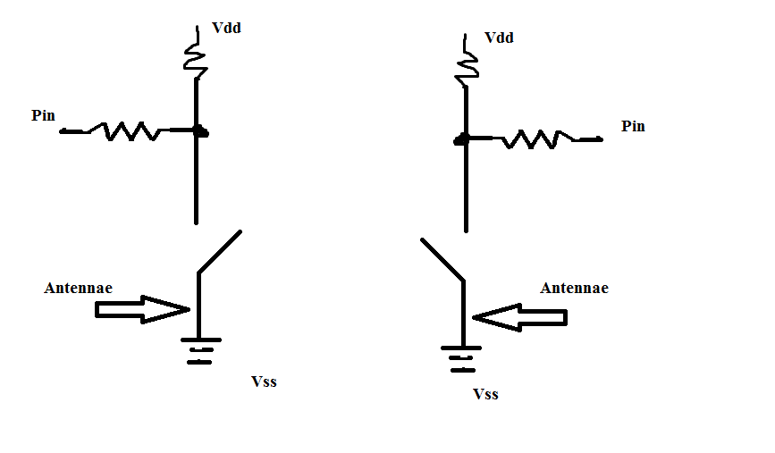
On the circuit board, there are two inlaid rings onto which stands (to which the antenna are fixed) are mounted. I wonder how this is related to the circuit diagram (see attachment). Why does connecting the antenna connect both antennae to the ground? Before the antenna are connected, isn't the antenna connected to ground (the chassis already)?
On the circuit board, there are two inlaid rings onto which stands (to which the antenna are fixed) are mounted. I wonder how this is related to the circuit diagram (see attachment). Why does connecting the antenna connect both antennae to the ground? Before the antenna are connected, isn't the antenna connected to ground (the chassis already)?
867 x 507 - 17K
Comments
So the pin is normally connected to ground (possibly with a weak resistor, though I don't think you really need it as long as you don't make the pin an output) but when the circuit is broken it is pulled high. At least that's the way I remember it. There are lots of different configuration that could work but I'm pretty sure all of this is pretty well described in the Robotics with the BOE-Bot book so it should be too hard to find the exact circuit they use.
Each whisker is both the mechanical extension and the ground electrical connection of a normally open, singlepole, single-throw switch. The reason the whiskers are connected to ground (Vss) is because the plated holes at the outer edge of the board are all connected to Vss. This is true for both the Board of Education and the BASIC Stamp HomeWork Board. The metal standoffs and screw provide the electrical connection to each whisker.
When the antenna (or whisker) hits something, it will bend back and contact the matching header on the breadboard, which is providing the other side of the switch circuit. Each input pin will be high until the whisker contacts the header, pulling the input low.
Page147 from Robotics with the BOE-Bot v3.0.pdf
The circuit in the manual has the two resistors on the input pins at 220 ohm, and the resistors to VDD at 10K.
The function of the whiskers and the circuit diagram make more sense now.