

Controlling 3 Servos With 3 Potentiometers
 mspicer
Posts: 8
mspicer
Posts: 8
I'm part of my high school's Robotics team and we're trying to build a robotic arm that makes use of three 180 degree rotation servos very similar to the ones from the "What's a Microcontroller" kit. I've been trying to write a program that allows me to control the three servos independently using three different potentiometers, and so far I've been unsuccessful.
Here's my latest attempt:
' {$STAMP BS2}
' {$PBASIC 2.5}
time1 VAR Word
time2 VAR Word
time3 VAR Word
DO
GOSUB GETtime1
PULSOUT 13, time1
GOSUB GETtime2
PULSOUT 14, time2
GOSUB GETtime3
PULSOUT 15, time3
LOOP
'
GETtime1:
HIGH 11
PAUSE 10
RCTIME 11, 1, time1
LOW 11
time1 = time1 */ 185
time1 = time1 +500
RETURN
'
GETtime2:
HIGH 7
PAUSE 10
RCTIME 7, 1, time2
LOW 7
time2 = time2 */ 185
time2 = time2 +500
RETURN
'
GETtime3:
HIGH 0
PAUSE 10
RCTIME 0, 1, time3
LOW 0
time3 = time3 */ 185
time3 = time3 +500
RETURN
Below, I've also attached a picture of my breadboard wiring. I'd really appreciate it if someone could guide me in the right direction!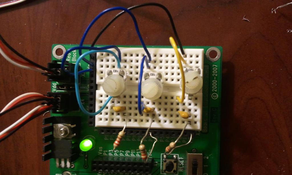

1024 x 614 - 71K
Comments
It's probably easier to use an external ADC (analog to digital converter) like the MCP3204 which has 4 channels and can be easily controlled by the Stamp and has some example programs (see the webstore page for a link for that).
http://www.ebay.com/itm/CCPM-Servo-Consistency-Master-Servo-tester-/140928657367?pt=US_Radio_Control_Control_Line&hash=item20d000a7d7#ht_2690wt_1208
http://www.youtube.com/watch?v=t5AyBeMdtMk demo
Edit: Dang you erco! You bet me by one minute. I may not have been as fast, but I think my reply was funnier (so there).
Any suggestions for getting my servo to turn more smoothly?
Here's my code if that helps..,
'
[ I/O Definitions ]
CS PIN 8 ' Chip Select (MCP3204.8)
Clock PIN 11 ' Clock (MCP3204.11)
DataOut PIN 4 ' Dout on ADC (MCP3204.10)
DataIn PIN 6 ' Din on ADC (MCP3204.9)
'
[ Constants ]
Cnts2Mv CON $0139 ' x 1.22 (To Millivolts)
'
[ Variables ]
result0 VAR Word ' Conversion Result CH0
result1 VAR Word ' Conversion Result CH1
result2 VAR Word ' Conversion Result CH2
result3 VAR Word ' Conversion Result CH3
mVolts0 VAR Word ' Result0 --> mVolts
mVolts1 VAR Word ' Result1 --> mVolts
mVolts2 VAR Word ' Result2 --> mVolts
mVolts3 VAR Word ' Result3 --> mVolts
please VAR Word
'
[ Init Setup ]
DEBUG CLS, "ADC CH 0 : ", CR, "Volts :", CR,
"ADC CH 1 : ", CR, "Volts :", CR,
"ADC CH 2 : ", CR, "Volts :", CR,
"ADC CH 3 : ", CR, "Volts :", CR
'
[ Program Code ]
DO
LOW CS
SHIFTOUT DataIn, Clock, MSBFIRST, [%11000\5 ] ' Select CH0, Single-Ended
SHIFTIN DataOut, Clock, MSBPOST, [result0\13] ' Read ADC
HIGH CS ' Disable ADC
mVolts0 = result0 */ Cnts2Mv ' Convert To Millivolts
LOW CS ' Enable ADC
SHIFTOUT DataIn, Clock, MSBFIRST, [%11001\5] ' Select CH1, Single-Ended
SHIFTIN DataOut, Clock, MSBPOST, [result1\13] ' Read ADC
HIGH CS ' Disable ADC
mVolts1 = result1 */ Cnts2Mv ' Convert To Millivolts
LOW CS ' Enable ADC
SHIFTOUT DataIn, Clock, MSBFIRST, [%11010\5] ' Select CH2, Single-Ended
SHIFTIN DataOut, Clock, MSBPOST, [result2\13] ' Read ADC
HIGH CS ' Disable ADC
mVolts2 = result2 */ Cnts2Mv ' Convert To Millivolts
LOW CS ' Enable ADC
SHIFTOUT DataIn, Clock, MSBFIRST, [%11011\5] ' Select CH3, Single-Ended
SHIFTIN DataOut, Clock, MSBPOST, [result3\13] ' Read ADC
HIGH CS ' Disable ADC
mVolts3 = result3 */ Cnts2Mv ' Convert To Millivolts
DEBUG HOME, CRSRXY, 11, 0, DEC result0, CLREOL, ' Displays voltages & digital value
CRSRXY, 11, 1, DEC mVolts0 DIG 3, ' for all four channels
".", DEC3 mVolts0,
CRSRXY, 11, 2, DEC result1, CLREOL,
CRSRXY, 11, 3, DEC mVolts1 DIG 3,
".", DEC3 mVolts1,
CRSRXY, 11, 4, DEC result2, CLREOL,
CRSRXY, 11, 5, DEC mVolts2 DIG 3,
".", DEC3 mVolts2,
CRSRXY, 11, 6, DEC result3, CLREOL,
CRSRXY, 11, 7, DEC mVolts3 DIG 3,
".", DEC3 mVolts3, CR, CR, CR
GOSUB Send_Pulses
PAUSE 100
LOOP
Send_Pulses:
result0 = result0 */ 52
result0 = result0 + 500
PULSOUT 13, result0
DEBUG DEC5 result0
RETURN
It may also be worth noting that nothing is connected to channels 2 or 3. Anyway, thanks again for the help!
Each servo needs a pulse every 20ms in order to hold its position. You want time of each loop through your program to add up to 20ms and you want to make sure each servo gets pulsed each loop.
I'm betting with your debug statements you don't need to add any pauses at all since your loop probably takes longer than 20ms without a delay. If the loop is just a little longer than 20ms, you shouldn't have a problem but if the loop takes a lot longer than 20ms, you may need to remove the debug statement.
I was able to control parallax standard servos from the What's a Microcontroller Kit using the MCP3204. However, the servos that I'm actually using for the project are Traxxas 2075 waterproof digital servos which came in today. When I swap in these servos to the same circuit ADC circuit in which the parallax servos were working, I get no response from them. When I run simple test programs, I can sometimes get them to turn but they seem to function very inconsistently.
According its spec sheet (http://www.servodatabase.com/servo/traxxas/2075) the Traxxas 2075 should run on the same 6 VDC as the parallax standard servo (https://docs.google.com/viewer?url=http%3A%2F%2Fwww.parallax.com%2FPortals%2F0%2FDownloads%2Fdocs%2Fprod%2Fmotors%2F900-00005-StdServo-v2.2.pdf).
Is it just that the pulse cycle and pulse width of the 2075 is different? If so, how would I find out what those values would be?
Even though my connections and power source all seem to be fine, the servos do not so much as flinch when I turn the power switch to position 2. Yet, like I said, the parallax standard servos function completely fine when they are plugged into the exact same pins as the traxxas servos.
One other thing I tried was to connect the red and black wires straight to the positive and negative terminals of a nine volt battery while wiring only the white wire to the BOE. When I did this and tried to turn the servo shaft, I definitely felt some resistance. But other than that, I can't seem to get these servos functioning. Is there any further testing I can do to determine what the problem is? Thanks again everyone for your advice!
Servos can draw a lot of current as they start to move. This can cause the voltage to drop which can cause the uC to reset. You are unlikely to see this voltage drop with a multimeter.
What are you using as a power source?
I think a good power source for your servos would be four (maybe five) AA NiMH batteries. Many wall-wart power supplies don't provide enough current for servos. 9V batteries do not provide enough current for many/most servos.
If you use a second power source for your servos you need to make sure the ground connections on both supplies are connected together.
I hope your servos still work after your 9V experiment. IMO, it wasn't a good idea since 9V is too high of a voltage for the servo.
BTW, We see lots of servo problems on the forum. Power supply issues are at the top of the list as the cause of the problem. It's also very common for the person looking for help to initially not believe it's a power supply issue.