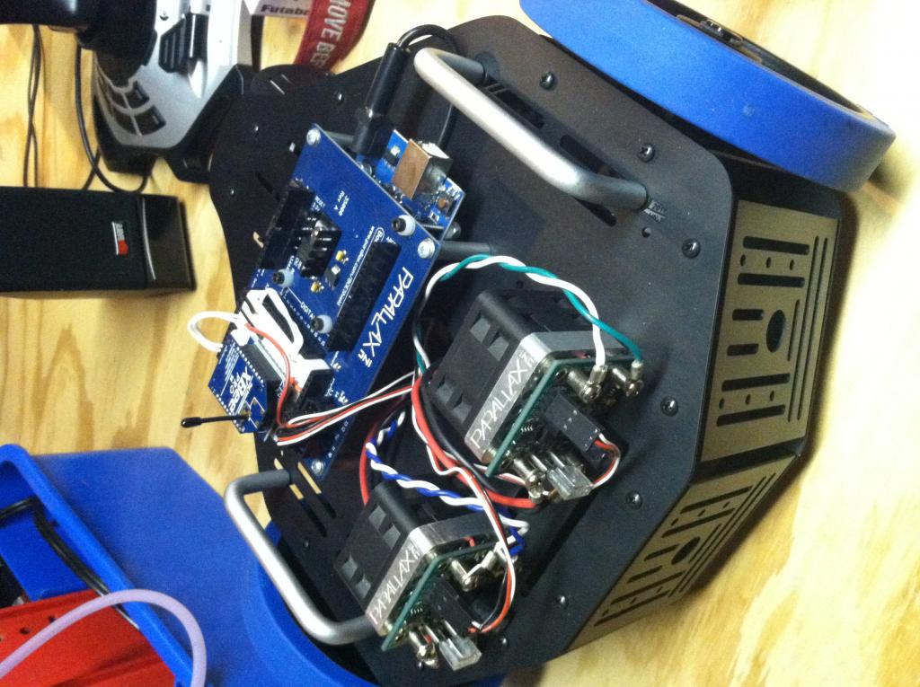
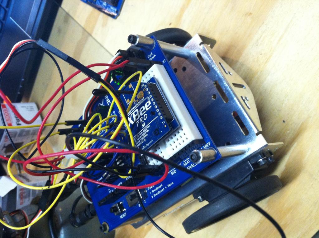
Parallax BOE shield for arduino
I have bought lots of parallax products in the past and always found lots of thought in the product design but unfortunatly the "BOE shield for Arduino" doesn't meet the quality i have seen in the past.
I bought 2 of these boards to play around with and so far this is what i have found:
1. The designated PWM pins on the Arduino (11,10,9,6,5,3) have not been identified on the PCB.
2. The there are 4 headers for servos but only 2 of them will work for servos (11,10) because pins 13 and 12 are not designated as PWM pins on the Arduino.
3. There are only 3 holes to hold the arduino to the shield when there could have been 4
I don't know if these were things that were just overlooked in the design process, or if they are like that for a reason.


Comments
You are right that labeling the pwm pins would have been a good idea, but I don't think it is as important as you believe. With regards to your second point. I've used servos on any pin, not just the pwm pins. This is because servo pulses are generated in software using timers, not the analogWrite API (which wouldn't work anyway). I've read the servo library and I didn't see any code restricting pins. Finally, four holes might be better, but not all Arduino boards have four. Here's a link to the original serial design :
http://arduino.cc/en/Main/ArduinoBoardSerialSingleSided3
As you can see it only has three holes. I own several freeduino boards and all of them only have three holes. So Parallax might be following some sort of convention.
As for marking the PWM-enabled pins, that's something that I always felt was clutter on the Arduino. Some Arduino-compatible boards don't have it either. If you know enough about PWM you'll know how to read the documentation that talks about which pins go to where, and more importantly which timers are involved with which pins. For anything beyond simple sketches the lack of timer ID makes what markings there are on the Arduino nearly useless. The Arduino Uno board doesn't mark which pin A4 or A5 is for IC2 data and clock. I2C is probably used more commonly than PWM, so it's not like there's consistency.
A fourth hole might have been nice. I'm not sure why it's not there, other than having to re-route some of the traces.
-- Gordon
Miles