Question about soldering a Parallax 27114 - Dual RelayBoard
Hi, anyone soldered one of these together???
What I found in the box isn't necessarily what Parallax said is in the package per the instructions...
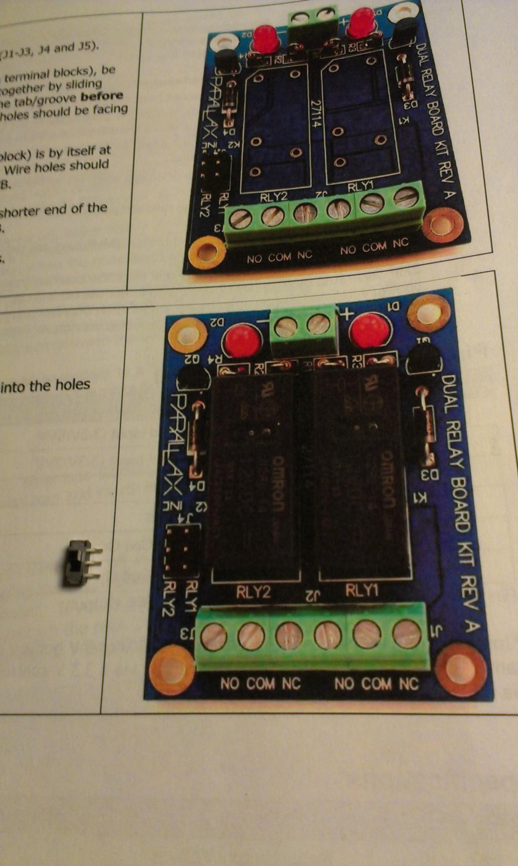
Namely this...This is what is on the instruction sheet:
J5 Connector, Header, 2x3,
0.1", Straight 1 450-00105
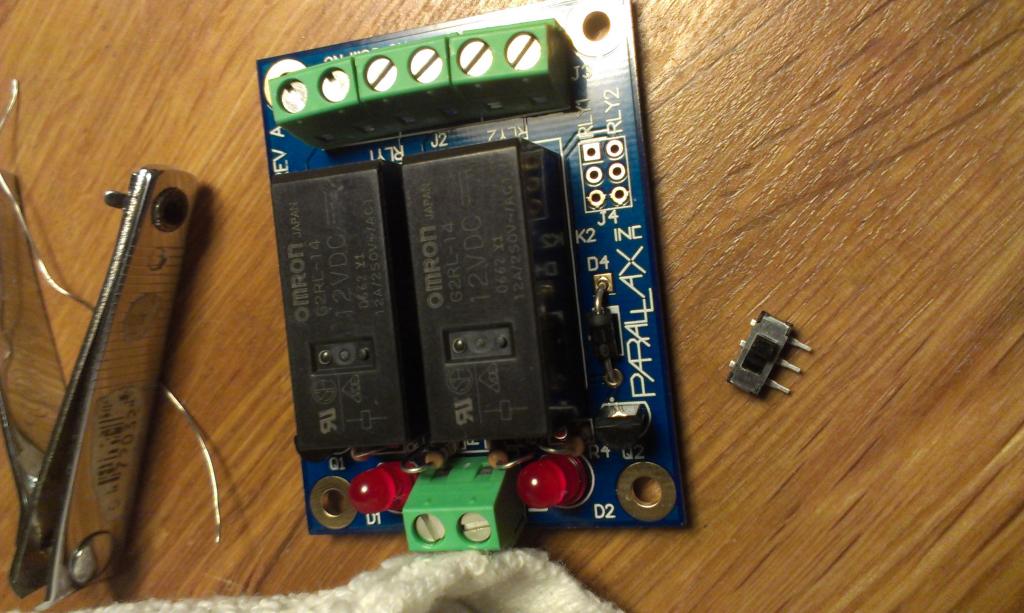
But what I found is this (see images attached)


So I have a two position switch in the package. But it's not clear how I should solder it. The instructions say, "
J4 should be installed with the shorter end of the
pins being inserted into the PCB. "
But there are no long or short ends of the pins!!! Who wrote these instructions?!!!! There are only 3 pins. They are all the same length.
Any thoughts??
Thanks,
gpierson
What I found in the box isn't necessarily what Parallax said is in the package per the instructions...
Namely this...This is what is on the instruction sheet:
J5 Connector, Header, 2x3,
0.1", Straight 1 450-00105
But what I found is this (see images attached)


So I have a two position switch in the package. But it's not clear how I should solder it. The instructions say, "
J4 should be installed with the shorter end of the
pins being inserted into the PCB. "
But there are no long or short ends of the pins!!! Who wrote these instructions?!!!! There are only 3 pins. They are all the same length.
Any thoughts??
Thanks,
gpierson


Comments
I would contact Parallax support; they'll make it right.
Well, at least I'm not going crazy! I was really scratching my head wondering what the little switch was for!
Thanks...
Gene.
Our apologies for the problem, too.
Never fear. Parallax will take care of the problem and then some. Ken & company never disappoint.