Exploring the Stingray Chassis Kit
Hello all,
I recently bought a Stingray Chassis Kit and I started the experimentation with it.
From my research I noticed some very useful links about this product:
1) Stingray Robot Kit Changes (#28980)
2) Stingray Robot Kit (#28980) and Wheel Encoders
3) Building and customizing Parallax Stingray, an ongoing project log
I think that stingray robot can be a very “OPEN” robot and users can complete this robot using a lot of different combinations of Parallax products.
Users can also put the accessories (microcontrollers, sensors, power pack, motor controllers, encoders) with a lot of different ways creating a big variety Stingray robots according to their needs and of course according to their budget.
In my lab I have a lot of Parallax products and my first dilemma was which of them I should use in order to create a complete and efficient robot.
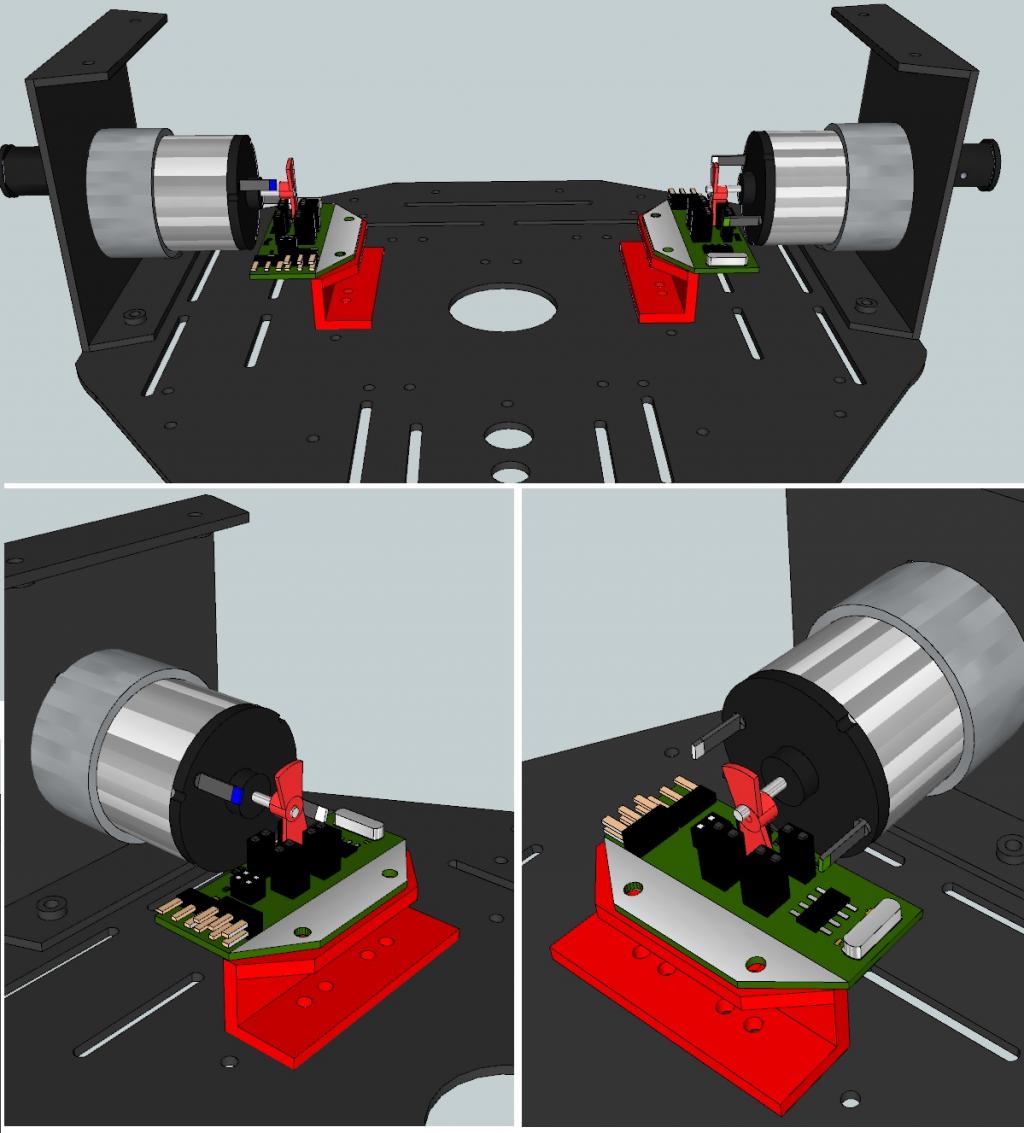
The first thing I did in order to help myself was the creation of a 3D Sketchup model of the Stingray Chassis Kit

This 3D model helped me a lot in order to decide the appropriate position for every accessory, and also it is helped me in order to design some useful plastic parts with my 3D printer.
My very first Stingray synthesis consisted of:
Stingray Chassis Kit
Main board: the Propeller Board of Education (#32900)
Motor controllers: 2 x HB-25 Motor Controllers (#29144)
Power pack: Li-ion Power Pack/Charger (#28986) and 2 X High-Capacity Li-ion Cells
Other hardware:
4 X Round Standoff 4/40, 0.625
1 X 3-pin Power-Signal-Ground Cable Extensions (6")
1 X 3-pin Power-Signal-Ground Cable Extensions (8")
Here is a connection diagram and a simple Spin code in order to make the robot move around (file: stingray_simple_test_with_HB-25_controllers.rar)

It is very useful to add an On/Off switch between Power pack and HB-25 Controllers.
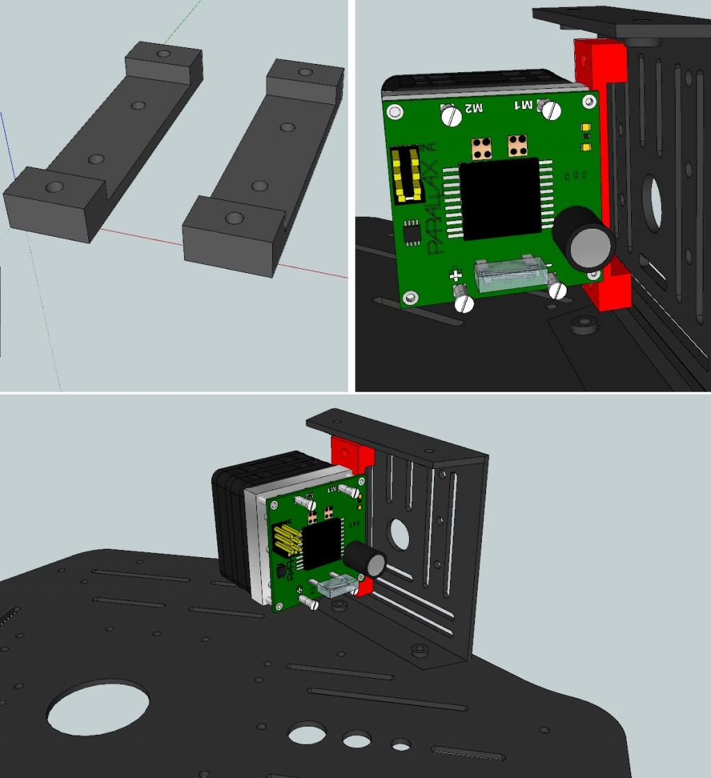
I made also a Mounting Bracket in order to adapt the HB-25 Motor Controllers into the Stingray’s Chassis:

My next step was the encoders.
I decided to convert the old Parallax Position Controller Kit (#27906) to a controller kit for the Stingray!

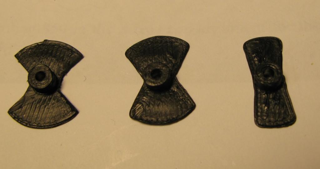
This conversion mechanically is very simple and very easy if you have a 3d Printer. The conversion kit consisted of a Mounting Bracket for the encoder and of a “flipper” for the Stingray motors. The flipper has only two blades instead of the 9 blades of the original kit because the new position of the flippers (directly on the motors axes) gives them more RPM. However I haven’t decided yet which should be exactly the right shape of the “flipper”. Here are some samples in which I’m working on.

From my tests I can say that the kit mechanically works perfectly.

The encoder is in the right distance from the motor and from the flipper and the motor can rotate without friction or any other problems.
At this stage I’m trying to develop the right spin code drivers for this kit conversion.
Using my parallax oscilloscope I’m trying to analyze the signal from the encoders as the motors rotate in order to choose the right flipper shape.
Here is the image that I got from the encoder signal using my oscilloscope :

Nikos G.
I recently bought a Stingray Chassis Kit and I started the experimentation with it.
From my research I noticed some very useful links about this product:
1) Stingray Robot Kit Changes (#28980)
2) Stingray Robot Kit (#28980) and Wheel Encoders
3) Building and customizing Parallax Stingray, an ongoing project log
I think that stingray robot can be a very “OPEN” robot and users can complete this robot using a lot of different combinations of Parallax products.
Users can also put the accessories (microcontrollers, sensors, power pack, motor controllers, encoders) with a lot of different ways creating a big variety Stingray robots according to their needs and of course according to their budget.
In my lab I have a lot of Parallax products and my first dilemma was which of them I should use in order to create a complete and efficient robot.
The first thing I did in order to help myself was the creation of a 3D Sketchup model of the Stingray Chassis Kit
This 3D model helped me a lot in order to decide the appropriate position for every accessory, and also it is helped me in order to design some useful plastic parts with my 3D printer.
My very first Stingray synthesis consisted of:
Stingray Chassis Kit
Main board: the Propeller Board of Education (#32900)
Motor controllers: 2 x HB-25 Motor Controllers (#29144)
Power pack: Li-ion Power Pack/Charger (#28986) and 2 X High-Capacity Li-ion Cells
Other hardware:
4 X Round Standoff 4/40, 0.625
1 X 3-pin Power-Signal-Ground Cable Extensions (6")
1 X 3-pin Power-Signal-Ground Cable Extensions (8")
Here is a connection diagram and a simple Spin code in order to make the robot move around (file: stingray_simple_test_with_HB-25_controllers.rar)
It is very useful to add an On/Off switch between Power pack and HB-25 Controllers.
I made also a Mounting Bracket in order to adapt the HB-25 Motor Controllers into the Stingray’s Chassis:
My next step was the encoders.
I decided to convert the old Parallax Position Controller Kit (#27906) to a controller kit for the Stingray!
This conversion mechanically is very simple and very easy if you have a 3d Printer. The conversion kit consisted of a Mounting Bracket for the encoder and of a “flipper” for the Stingray motors. The flipper has only two blades instead of the 9 blades of the original kit because the new position of the flippers (directly on the motors axes) gives them more RPM. However I haven’t decided yet which should be exactly the right shape of the “flipper”. Here are some samples in which I’m working on.
From my tests I can say that the kit mechanically works perfectly.
The encoder is in the right distance from the motor and from the flipper and the motor can rotate without friction or any other problems.
At this stage I’m trying to develop the right spin code drivers for this kit conversion.
Using my parallax oscilloscope I’m trying to analyze the signal from the encoders as the motors rotate in order to choose the right flipper shape.
Here is the image that I got from the encoder signal using my oscilloscope :
Nikos G.


Comments
We gotta get these kids together!
I noticed your Stingray encoder approach.
Did you use the Boe-Bot Digital Encoder Kit (#28107)?
One of my firlst thoughts was to to use these encoders in conjunction with a plastic" cap- rim" ( disc wheel ) with appropriate holes adapted on the inner side of stingray's wheels. I think this is also a very good solution!
Real men scratch-build their encoders. Mine & smelt the copper, for starters!
No, I'm using the $1 Rodan sensors from EG mentioned in the post you referenced.
It sure would make the placement of "things" much easier.
I hate to be that guy, but, would you be willing to share a copy of your Sketched-up Stingray?
I do see Lots of people are putting the control board on top of the Stingray,
I must be doing it wrong...
Anyways, thanks for sharing NikosG.
-Tommy
Of course here is the 3D model. ( Last time I posted here I tried to upload the model but for some reason it wasn't possible)
Although I haven't finished yet the wheels you can test your Stingray synthesis using my 3D model.
If you makes any updates of the model (e.g. the Wheels please send me a message)
Keep the great work with Stingray!
Nikos
Added a switch and charging receptacle to that little unused area above the rear wheel. This allows powering-up the HB-25s and motors separately from the Prop BOE board and gives me a way to charge the Li-ion Power Pack without removing the Stingray's top plate.
Also shown is a relay board for dynamic braking. 1 or 2 Prop pins set the relays to swap from powered mode to shorted leads, providing decent braking.
Nikos, I spent 7 weeks last year in Loutraki, Greece, not too far from Patras! Had I known there was a Propeller-dude close by I would have tried to look you up...
dgately
I like your switch position. I think you have chosen the best place for it!
The charger input that you suggest is also very nice idea! Personally I have been dreaming of a docking station that my Stingray can drive into for charging. I dont know if your charger input is the appropriate, but I think that it is placed in the right position for a docking station! Have you ever thought the docking station charging for your stingray robot?
I have a comment about the HB25 motor controllers.
As you can see I have put the HB-25 in the opposite direction than your robot. I put them in this direction because the outgoing air from HB-25s fans goes towards to DC motors and it can cool them! (Parallaxs technicians can tell us if I have right). So we can keep the motors with a lower temperature after a long time of use.
P.s. Greece is always the best place for summer holidays! We have a lot of places here that you can have a good time and enjoy yourself! Let me know if you came back in Greece! You are welcome!
Nikos.
I had not thought too much about docking as I'm still just trying to get my head around making the bot autonomous and not just controlled by wireless... Once I can get the motors to drive correctly (their speed does not match-up well yet. I'm working on a feedback/PID system to correct that) I'll work on better charging ideas.
I've been to Greece quite a few times as my wife's family lives in Athens (Paleo Faliron, to be exact). So, I'm there at least once a year. When I travel there again, I may look you up!
dgately
This is great! Dont forget to put some robots in your suitcase
Nikos.
You are of course welcome to use it anyway you see fit.
I do like where you have placed your on/off switch dgately, it looks clean...
I thought about placing mine there too, Only problem, It would interfere with my Anti-Caster Rudder Steering System...
So, when I put the on/off switch onto my Stingray, I remembered that many Line Following Competitions require an easy to access OFF switch,
For in case of a run-away robot, it can be deactivated quickly. I thought the best place for that would be right on top, and all by itself.
The switch is also oriented so that a flying dive, and outstretched hand, grasping for the switch, has a slightly better chance of success...
Anyway, thanks again NikosG, Your Sketchup of the Stingray is a real treat. :thumb::thumb:
-Tommy
As far as the control board being on top, I chose to mount mine there because it makes life easy! I had originally wanted to fit everything inside the sting ray, but that is just inconvenient for testing. I updated my thread(Nikos posted a link in post#1) last night with shots of the control board I just finished.Although it is on the top right now, I have plans to add one or two more decks to the stingray later.
Your thread is actually very crucial for many Stingray issues like the clocking of the Stingrays motors!!!
You have also suggested a nice way to keep Stingrays chassis stable and you can protect it from damages during the testings stage using your old erector sets.
I agree with you that are wise to protect the stingrays chassis during the tests and make our life easier avoiding any damage.
For this purpose I also have a suggestion very convenient for those who have a 3D printer.
My suggestion is a chassis frame. Users can put this frame on the top of the open Stingray when they work on it, doing their tests with the robot.
You have done excellent and detailed work with your Stingray!
Nikos
An approval from you has a special value!
However Im still not sure about the old encoders conversion. I think that motors are too fast for these encoders.
I would be thankful if you could give me any recommendation.
P.s. I will take the chance to ask for the prospective original Styngray encoders. Are ready for sale?
Nikos
Would live to use a frame like this.
Thanks,
jt
I also send the zip file with the sketchup model here.
Have fun with your Stingray robot!
Yes of course theoretically you can print the entire Stingray chassis if you have a 3d printer but the result will be by far with lower quality from the original chassis!
ABS (and the others 3D printer material) are not strong enough in order to create a model like the original.
You should change the dimensions. Definitely you must change the thickness of every part and the entire result will be very different and of course with lower stability and quality!
In my opinion 3D printers are good enough to replicate plastic parts. For instance if you have a Lego NXT robot, you can use your 3d printer in order to replicate some plastic components.
Parallax robots have an incredible quality (aluminum chassis and a lot of other details) that it is impossible to replicate them, using home machines. If you want to make a modest replica of the Boe bot or the Stingray you must have industrial machines and equipment.
However using an affordable 3d printer you can make some useful accessories like brackets, mounts etc. and you can save some money! I think that the real value of the 3d printer is the experimentation in order to test some new ideas of accessories
I apologize for the delays on this product. As far as I knew they were done and ready to be kitted. I'm hoping Matt Gilliland can step in and offer a more up to date response. We should really have these available, but red tape and all.
I added a switch on the back of my Stingray chassis too. Just below it I installed a small voltmeter module so I could keep tabs on the battery. I have the external charger jack located elsewhere in a plastic cover.
Nice! I just eBay-purchased several voltmeter modules and was thinking of where one would go on the Stingray...
dgately
Very nice! As a note, the hole back there was designed for a 12V Automotive (or similar) power switch.