RaspberryPi Soft Switch PCB check
So this is my first modestly complicated SMT PCB design and I wanted to get feedback from the hive on what I have thus far, Basic theory is that a PICAXE 08M2 is used to monitor a push-button switch to signal when to turn on. After turning on, the Raspberry can send a KILL signal to turn off it's own power 10 seconds after the KILL line floats back up to logic H. The user can press the button briefly to tell the Pi to do a powerdown, or the user can hold the button down to force an immediate power down. The PICAXE switches to 32KHz clock when it's in the OFF state and draws about 35uA. MOSFET I had on hand was a logic level P-Chan that has a max rating of 25A. As this is I suspect 2-3A would be the maximum.
The ADC allows for the Pi to sense battery voltage and shutdown while there is some reserve remaining. Tried to move the ADC as far from the MOSFET as possible to reduce any temperature variation in readings from the local heating that MOSFET might generate. On-board regulator for 3.3V is very low quiescent current but adds about 15uA to the off-state current drain. The ADC adds another 1uA when not doing a conversion.
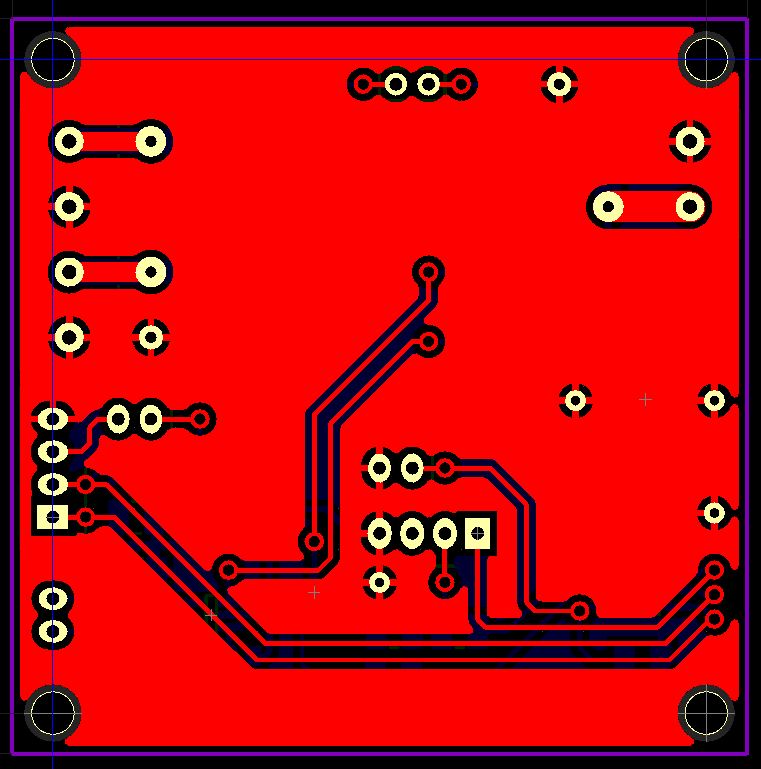
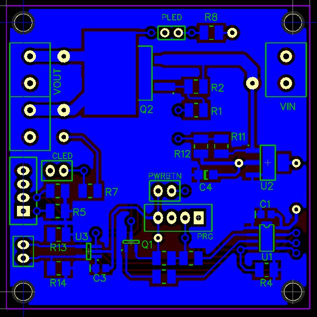
TOP

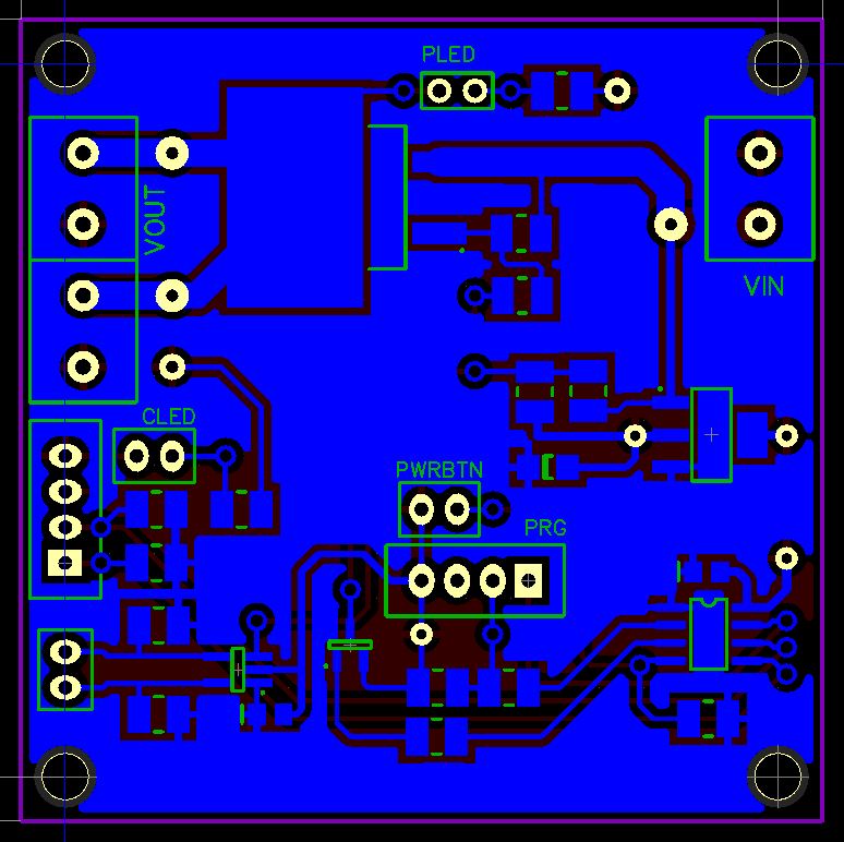
BOTTOM

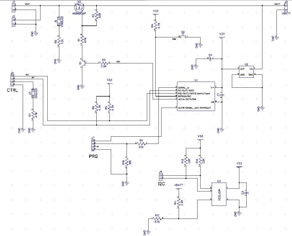
SCH

Let me have it!


The ADC allows for the Pi to sense battery voltage and shutdown while there is some reserve remaining. Tried to move the ADC as far from the MOSFET as possible to reduce any temperature variation in readings from the local heating that MOSFET might generate. On-board regulator for 3.3V is very low quiescent current but adds about 15uA to the off-state current drain. The ADC adds another 1uA when not doing a conversion.
TOP
BOTTOM
SCH
Let me have it!


Comments
you need to calculate the heat dissipation (the current rating is merely an indication of the max power
rating under infinite heat-sink conditions - there are devices where the current rating is larger than the
current that damages the packaging / bonding wires!)
[btw layout looks OK - you could get the board size down a bit, but if you are hand-soldering it is
probably wise not to. Perhaps a few more ground vias?]
The MOSFET actually has a little bit lower than average RDS(on) so it burns less wattage passing the current. I calculated the heat based on the case-to-air thermal specs and the numbers say 4A should be safe. 4A is 800mW and a junction temp of 102C. My small bot is a stepper based system that draws a maximum of about 2A, for 200mW and junction temp of 60C. I have plans for a larger bot later but it would have a separate motor supply with switching that was tied to the state of the logic power but not directly connected.
Again, thanks for giving me some feedback. I'm going to start on the prototype this weekend. The SMD PICAXE's are on their way. I really wish a US outlet would start supplying those. I know I could go to a bare PIC or AVR but this is nice for getting the overall design worked out and they are easy to interface to.