

Omni Wheel Configuration
 BrainStrain
Posts: 30
BrainStrain
Posts: 30
I have reached the point in my Standing Wheel Chair project where it is time to build the motorized omni wheel base. Oh, yeah, almost forgot. I have built a working standing chair prototype. I am very pleased with the design. It works and I have stood up several young ladies who are paralyzed below the waist. I can hardly wait to test it with powered wheels. I had three paraplegic young ladies at my house to test the chair a couple of months ago. I thought they would be excited at the prospect of scooting around the house standing so they could cook, wash dishes, brush their teeth, etc. But they got all giggly at the thought of standing up to put on their make up!
So the first step in building Prototype II is to design and build a running omni wheel base. Then I can design the rest of the chair frame around it. I have attached a picture of an omni wheel attached to my test mount. I am going to use short bicycle chains to run the wheels.
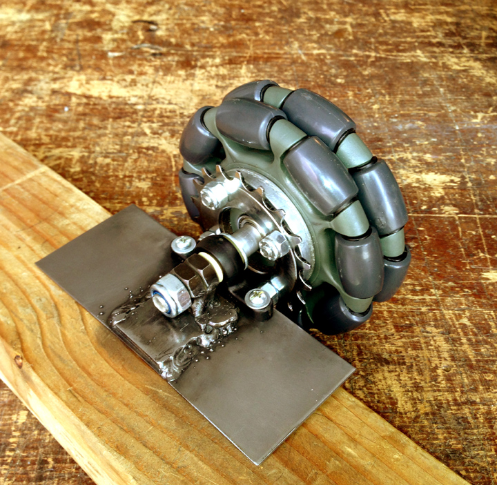
After spending a chunk of time drawing possible wheel base configurations, I ran into an omni wheel configuration issue. First, I am going to use three omni wheels; two at the corners of the chair front, and one centered in the back. I can't use an equilateral triangle to position the wheels because in order to properly support the chair the triangle would be too large to fit through door ways. So I stretched the triangle until the rear wheel fit where it needed to. This led me to drawing and calculating angles for the front wheels and various circumcenter points for my new triangle(s) so I could get the chair to spin left and spin right somewhat centered from the rider's perspective. I can't have the chair gyrating around like an out-of-balance washing machine. During this exercise, I realized that I could not position the front omni wheels much below 45 degrees relative to the front of the chair because of the loss of "omni" function and a battery-killing loss of efficiency. As you move the angle of the wheels closer to parallel with the front of the chair, they begin to point at each other. That is good for spinning in circles and going sideways, but at some point the wheels would completely lose the ability to move the chair forward and backwards. Every degree of change puts the wheels in position to fight against each other more and more, which spells dead batteries.
So, I was thinking that I might want to angle the wheels as much as 60 degrees relative to the front of the chair. This would maximize the efficiency of going forward and backwards because every change in degree points the wheels more in the forward direction. And forward, or almost forward, is the direction the rider will be moving most of the time. However, this would make the spin left and spin right geometry somewhat complicated. So, finally, my question is, can I position the wheels at about 60 degrees and then correct the behavior of the wheel base's motion with programming, or do omni wheels demand that I position them at 45 degrees?
So the first step in building Prototype II is to design and build a running omni wheel base. Then I can design the rest of the chair frame around it. I have attached a picture of an omni wheel attached to my test mount. I am going to use short bicycle chains to run the wheels.
After spending a chunk of time drawing possible wheel base configurations, I ran into an omni wheel configuration issue. First, I am going to use three omni wheels; two at the corners of the chair front, and one centered in the back. I can't use an equilateral triangle to position the wheels because in order to properly support the chair the triangle would be too large to fit through door ways. So I stretched the triangle until the rear wheel fit where it needed to. This led me to drawing and calculating angles for the front wheels and various circumcenter points for my new triangle(s) so I could get the chair to spin left and spin right somewhat centered from the rider's perspective. I can't have the chair gyrating around like an out-of-balance washing machine. During this exercise, I realized that I could not position the front omni wheels much below 45 degrees relative to the front of the chair because of the loss of "omni" function and a battery-killing loss of efficiency. As you move the angle of the wheels closer to parallel with the front of the chair, they begin to point at each other. That is good for spinning in circles and going sideways, but at some point the wheels would completely lose the ability to move the chair forward and backwards. Every degree of change puts the wheels in position to fight against each other more and more, which spells dead batteries.
So, I was thinking that I might want to angle the wheels as much as 60 degrees relative to the front of the chair. This would maximize the efficiency of going forward and backwards because every change in degree points the wheels more in the forward direction. And forward, or almost forward, is the direction the rider will be moving most of the time. However, this would make the spin left and spin right geometry somewhat complicated. So, finally, my question is, can I position the wheels at about 60 degrees and then correct the behavior of the wheel base's motion with programming, or do omni wheels demand that I position them at 45 degrees?

720 x 703 - 383K
Comments
I thought this was the "standard" configuration for three omni wheels.
I haven't done a lot of testing with three omni wheels yet, but it's on my todo list.
I have found my omni wheel bot doesn't drive in a straight line on carpet (the only surface I've tested it on) when the wheels aren't distributed symetrically around the line of travel.
In the picture above, let's call the wheel closest to the camera the back wheel. The robot will travel straight if I give it a command to travel forward of backward but travelling to the side isn't as easy.
My control algorithm computes the wheel speed based on the wheels angle to the line of travel but the actual direction of travel is a little off from the computed direction. This isn't noticeable when I'm controlling the robot by remote so I doubt it would be a problem if your robot is being guided by a human.
Here's my robot driving in a figure 8 as part of erco's figure eight challenge.
I thought the 45 degree configuration was used with four omni wheels?
I think just about any angle could be used (within reason) as long as the correct angles were used in the algorithm to compute wheels speeds.
I haven't seen any algorithms for computing wheel speeds on these types of omni wheels online (not that I've looked very hard). The algorithm I came up with seems to work pretty well and I'd be happy to share it if you'd like. It's not really very complicated IIRC it computes the individual wheels speeds by multiplying target speed of the robot by the cosine of the angle the wheel makes with the line of travel (sorry if you already know this).
I'm pretty sure there are modifications to the algorithm that would improve it's ability to travel in a straight line when the wheel directions aren't symmetrical.
Let me know if you'd like me to post the code I have.
Edit: I see I've already posted the code. I'm still very willing to help.
However, that still leaves me with a second issue, which is how to get the wheel chair to spin left or right and otherwise steer correctly when the circumcenter for the wheel base is a mismatch with the center of the chair and the vertical position of the rider's head. Remember, I stretched the rear wheel backwards about 4.5" past where it would have been for an equilateral triangle.
Now that my drawing is fixed I think the next step will be to build the wheel base. Then I will take a serious look at your code, and I very much appreciate your offer to help! I certainly need some help to bring this project to fruition. I am very much looking forward to the moment when I connect the wheel base to my three-axis joy stick and start testing code. By the way, I have progressed far enough with my joy stick programming that I think I'm ready to work on the motor control. Very exciting times.
When I eventually get the omni wheels running based on a equilateral triangle configuration, then I'll see how the chair performs and make adjustments to a desirable circumcenter point.
And, no, I have not already figured out the trig to coordinate the wheels. It's been about 40 years since I've been in a math class, so my trig is a bit rusty.
Before I forget, there is a good circumcenter calculator at:
http://easycalculation.com/analytical/circumcenter-triangle-calculator.php
Thank you again, Duane, for your willingness to help.
In most omni wheel designs I've seen, when all the wheels are turning at the same speed the robot will rotate about its center. I think this is one of your concerns since your configuration may need a modified algorithm for turning in place.
I don't think this modification will be very difficult. It will just require a little additional math compared to more conventional configurations.
I do think your configuration may cause some practical problems. It seems like there would be an advantage if the mass of the robot could be evenly distributed across the three wheels. If the mass can't be evenly distributed over the three wheels, I'd think it would be better to have the mass closer to two of the wheels rather than closer to a single wheel. I'd think you would probably be better off if you had the two wheels at the back of the robot rather than the front of the robot since the center of mass of the robot will likely be towards its rear.
I wonder if some consideration should be given to the likelihood the robot will spend more time travelling forward than other directions. Is there a wheel geometry that favors forward motion?
Writing this last question reminds me of an advantage Mecanum wheels have over the wheels you're using. All four motors turn may turn at there full speeds when travelling forward with Mecanum wheels. These other omni wheels require at least one of the wheels to turn at less than full speed.
I agree with you completely about distributing the load on the wheels. We don't want the rear wheel and motor to take too much of the load. I plan to put two swivel casters behind the rear corners of the chair. Together with the centered rear omni wheel they should provide plenty of support. The omni wheels I'm using are rated for 250 lbs each. I don't like using casters, but even if I used four omni/mecanum wheels, the chair needs to have a couple of wheels a few extra inches behind the rider so she can't tip over backwards.
I say the rider is "she" because the first riders will all be women, the girls on Chelsie's HotWheelz wheel chair dance team:
http://www.facebook.com/TeamHotwheelz
http://montereybayareanews.com/2013wheelchairs-wont-slow-these-women-down/
I have included a picture of my styrofoam mock-up chair with the WowWee Tri-Bot base for you.
Oops, my 9000th post. Who knew???
Actually Whit did, he PM'ed me that I was fast approaching #9000! Although only a dozen of those actually contained any useful information.
PS: Don't let this happen to you!
Slick video riding the bike, fast! I've talked to my wife about converting our bikes to electric. That would call for a lull in my wheel chair project.
Here is a picture of a motor connected to an omni wheel for testing. I ordered the motor with a mounting bracket. The $10 for the bracket was well worth the money because it gave me templates for both the motor gear head profile and the mounting holes. Note that in this picture my wheel mount is facing with the top up, as it should be. Testing the motor driving the wheel with a chain on the bench worked out well. It showed me that the sprockets needed to be better aligned. I made an adjustment to the way the sprockets were mounted to the wheels. Now they run as smoothly as I could hope for. All is well.
I have attached some pictures to show how my motor/wheel hookup stands at the moment. I had to prop it up to take a picture of it. When I was doing that I got a wild idea and flipped the assembly over, upside down. It balanced beautifully and simply stood there in front of me. If anyone asks, I just might say I planned it that way
.
Today the Walk and Roll Foundation posted a link to a piece Chelsie did on CNN recently. I'd forgotten that there was a CNN surprise meeting as part of her recent trip to the Abilities Expo in Atlanta:
http://www.cnn.com/video/?hpt=he_mid#/video/health/2013/03/28/hm-wheelchair-dancing.cnn
Today UPS delivered a major part I needed to start the lower chair frame. Now I'm ready to dive in.... except I have to get my taxes done first....
\
I keep thinking about those omni wheels you have. Those are metal rollers right? I'm afraid those rollers are going to end up tearing up flooring wherever they go. I'd think they'd gouge hardwood and vinyl flooring even carpet might not be able to handle frequent passage of those wheels.
I'd think some sort of hard rubber roller would be needed to both protect floors and smooth out the ride.
Vex has a new "Pro" line of products. There have some larger omni and Mecanum wheels that look pretty tough. I wonder if they have something that would be useful for this project?
I just really worry about those metal rollers tearing up flooring.
The wheels are made by Rotacaster and sold by Magnus Mobility. The rollers are made of a very tough polyurethane, suitable for hand trucks, loading docs, pavement. One of the executives at Magnus assured me the wheels would not damage hard wood or vinyl floors. Time will tell for that. Rotacaster is coming out, maybe this month, with a softer roller. The new rollers are still supposed to wear very well. I'm looking forward to buying a set of wheels with the new rollers.
Thanks for the clarification.
First I tinkered around with designing the beginnings of a frame out of wood before I welded one up. The last thing I wanted to do was make a steel frame and then have to make multiple changes to it... as in throwing it out and starting over. Once I got a wooden mock-up designed and built I decided to make a 3D CAD file of it before I made one out of steel. I needed to start learning CAD anyway. It took a few sessions to learn enough of Google's SketchUp program to draw the frame, but I got it done. I plan to draw as many parts as I can in SketchUp. One thing the program did for me was give me exact dimensions, better than I could measure manually. Finally I made the unit out of steel. All went well. Now it is time to go vertical with the frame. I'll get the wheels/motors mounted and then move on to the rest of the chair. Tricky business.
Now it is time for motor control. I hooked up three Pololu 24v23 controllers to my 12V batteries, wired for 24 volts. Then I connected a Pololu controller to my Propeller Proto USB board that I've been using for my joy stick work. I could not get a controller to make a motor run, or even twitch. I used Pololu's Serial Transmitter software on my PC and got a motor running at different speeds, forward and reverse through a USB cable. I studied Pololu's PDF document, Simple_Motor_Controllers.PDF and used the four-byte and five-byte hex code they showed as examples. So I have gathered a basic understanding of the hex values used to run the controllers, but that did not translate into my beginner SPIN programming. I found some code in the forums that Beau Schwabe and Zhen Hua came up with in 2010; FMS Serial Joystick DEMO Driver v1.0.a. Their code looked something like what I am attempting, so I was encouraged by that. I am using Pololu's auto-sensing baud rate, so the hex code starts with $AA, as required. I have not yet figured out just how the controller wants to see the transmitted signal, so I won't consume a bunch of verbiage speculating about it here. This is basically the code I tried:
PUB MotorTest
dira [16]~~
outa [16]~~
'pst.StartPST (9600)
pst.start (17, 16, 0, 9600) '(rxpin, txpin, mode, baudrate)
repeat
pst.tx ($AA) 'Specifies Pololu auto baud rate sensing
pst.tx ($0d) 'Controller is Pololu device # 13.
pst.tx ($05) 'Set motor forward command byte with most significant bit cleared
pst.tx ($00) 'Data byte 1
pst.tx ($32) 'Data byte 2, hex 32 = half speed.
Oh, I'm in learning mode when it comes to clearing most significant bits.
I am just using the RX pin from the controller and a ground (VSS). That appears to be the simplest requirement in the Pololu PDF document. If anyone can help me get one of my motors to spin, I will be on my way to motor control. Of course, once I get the Prop and the controllers communicating, then the fun begins!
I have included a few pictures of my wiring and Prop, joystick set up. I made the motor controller connections to the batteries and then stacked the Prop with the joy stick on top. The picture shows many too many wires connected to the controllers. I took most of those off, as noted above.
Thanks